This lab works best a follow up to Software Defined Radio Assignment - Exploring the RF Spectrum with RTL-SDR and GQRX.

Note before you begin: If you are having trouble viewing these lab instructions, I recommend using Firefox on a desktop computer or laptop (not mobile device)

Objectives

The objective of this lab is to:
  1. Explore minimodem (general-purpose software audio FSK modem) for digitally transferring data between computers by sound.
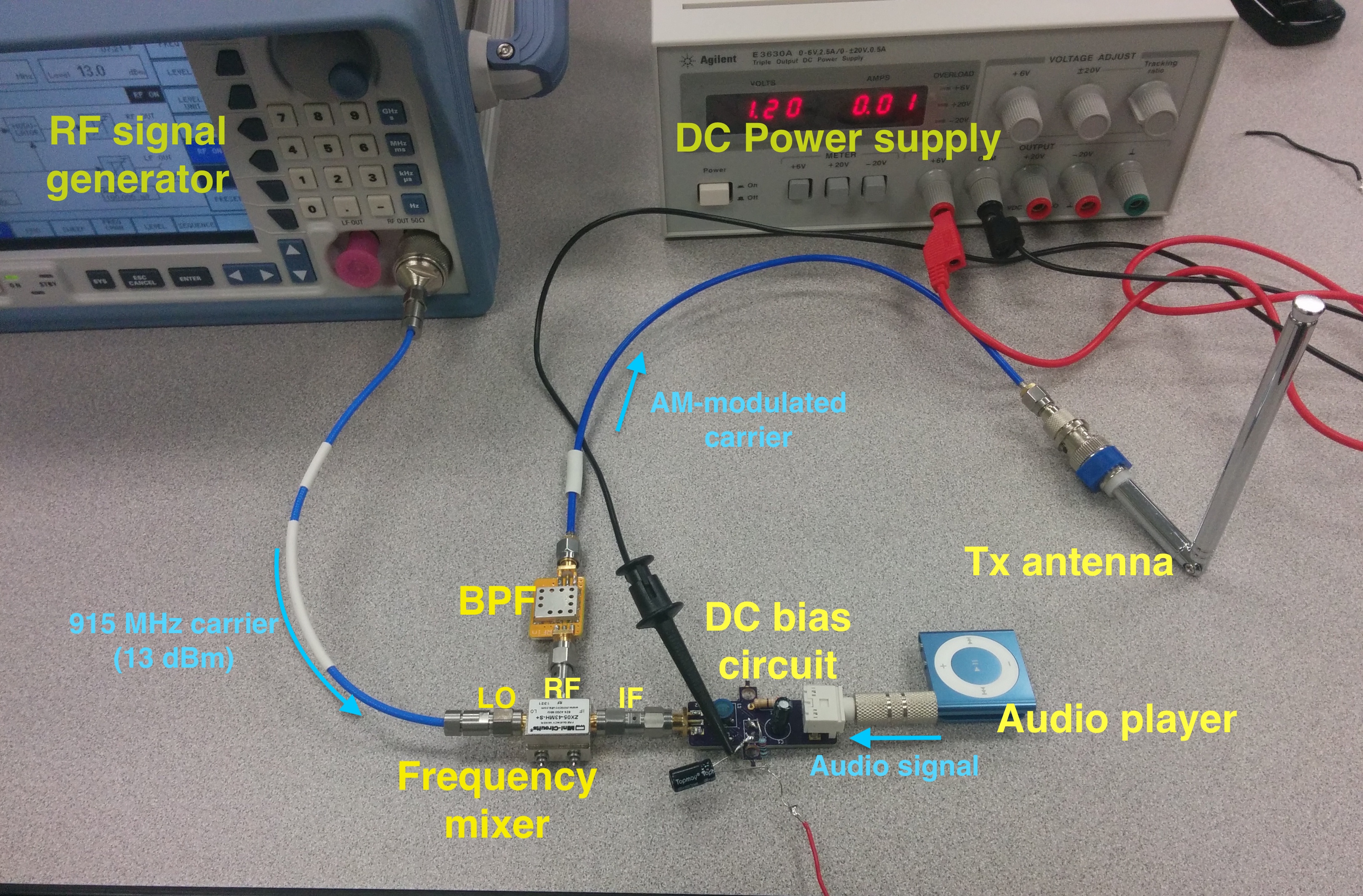
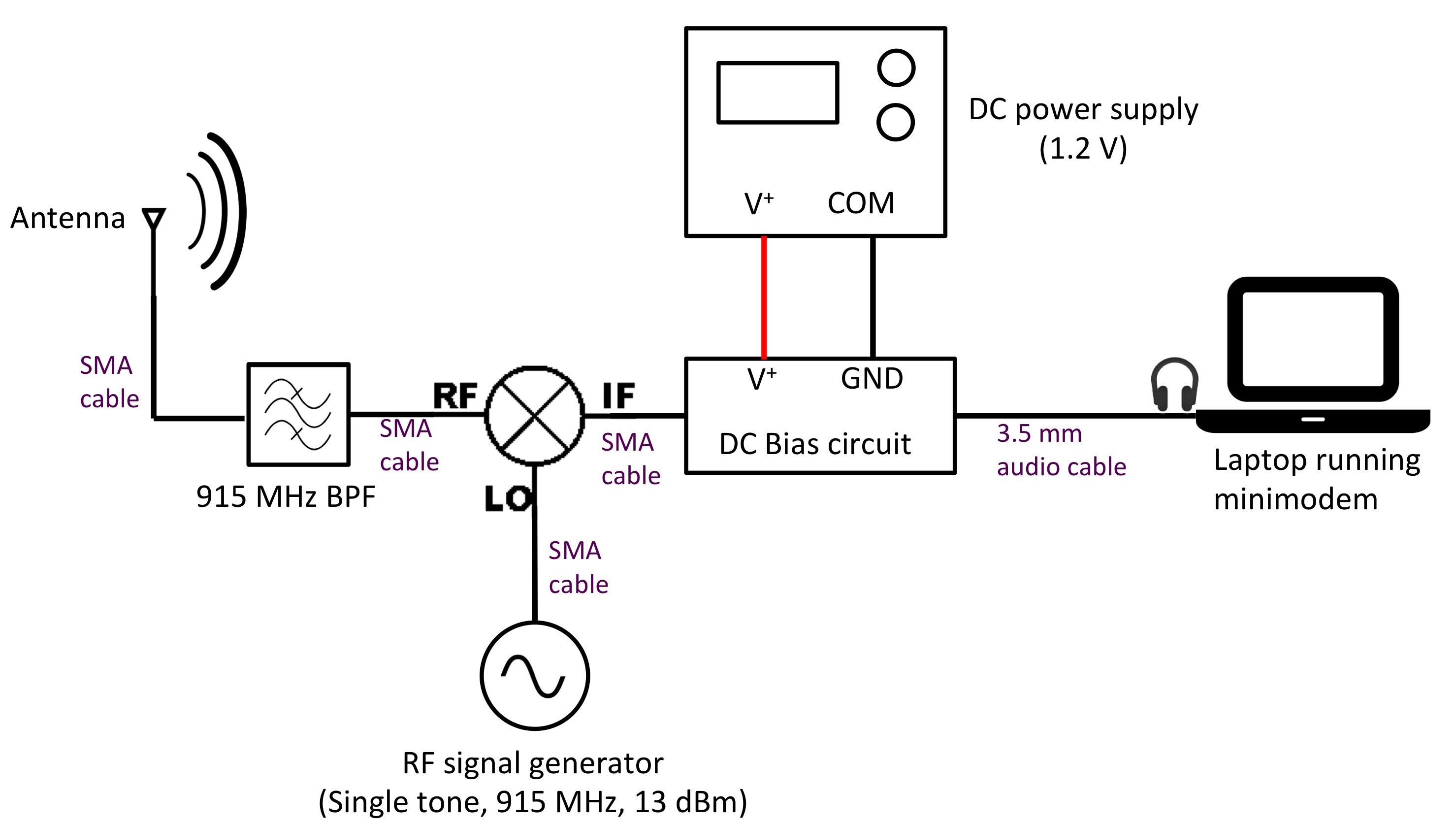
  2. Build a simple AM radio transmitter using an RF signal generator, Minicircuits frequency mixer, bandpass filter, audio source, DC bias circuit, and antenna.
  3. Explore receiving AM radio signals with a hand-held radio receiver and an RTL-SDR dongle.
  4. Combine the capabilities, knowledge and skills learned in first three objectives for building a packet radio for transmitting and receiving digital data.


Equipment

Here is a link to a comprehensive list of lab equipment available at Oregon Tech Wilsonville - DSP/Communicaitons Laboratory. For this lab you will need the following equipment and materials:
  1. One RF signal generator (requirements: frequency = 915 MHz, output power = 13 dBm).
  2. One DC power supply (minimum requirements: adjustable between 0 - 2 V DC).
  3. Two general computers (PC or laptop). At least one of the computers should have separate headphone and mic jacks.
  4. One MP3 player (or a computer or smartphone that can play music).
  5. One handheld AM radio receiver that covers 915 MHz, such as the Icom IC-R20.
  6. RTL-SDR stick, such as the inexpensive NooElec NESDR Mini 2 SDR USB dongle.
  7. Two bootable USB flash drive which Ubuntu Linux and and the GNU Radio Live SDR Environment pre-installed. If you would like to create your own bootable USB flash drive, follow the instructions here: Step-by-step: How to create bootable USB stick with GNU Radio Live SDR Environment.
  8. Two antennas for transmitting and receiving 915 MHz
  9. One 915 MHz narrowband bandpass filter (optional but recommended)
  10. One custom DC bias circuit. Circuit diagram. Gerber files (coming soon!).
  11. Mini-Circuits mixer (ZX05-43MH-S+). Data sheet
  12. Two shielded male to male 3.5 mm audio cables
  13. One or two short SMA coaxial cable assemblies.
  14. Two short alligator test lead clip to banana plug probe cables
  15. Adaptors: You may need the following adapters:
    • SMA (male to male)
    • SMA-to-BNC

Report guidelines

For the lab report, you will create a PowerPoint presentation (or use a similar presentation program), save it as a PDF, and submit it on-line according to the instructions given in class.

Your presentation will have 19 slides. Please include a slide number in the footer of each slide. To earn full credit your presentation must contain the slides in the order asked for in this lab. If you miss a slide, please leave a blank slide in its place so that you still have exactly 19 slides total. Your first slide should be:

Explore minimodem

  1. Connect a bootable USB flash drive to each of the two computers. The computers should be physically placed side-by-side (it would help if at least one of these computers was a laptop). For both computers, boot Ubuntu from their respective USB drives.
  2. Do this for both computers: In Ubuntu, click on the terminal icon. Type "minimodem". Hopefully, you will see a screen which specifies the usage and options in minimodem. However, if you get an error message that says something like "command not found", then you will need to download and install the program minimodem by following the directions on http://www.whence.com/minimodem/.
  3. Do you ever talk to yourself? Well, in this experiment you are going to make a computer talk to itself. Choose one computer to be the "subject" of this first experiment. This computer should be a laptop with built-in speakers and an external microphone. If you do not have access to laptop (or a PC with speakers and a mic), then consult your lab instructor. Turn the volume down to about 40% of max. Open up two separate terminal windows. In one of the terminal windows type "minimodem --rx 100" and press enter (I will refer to this terminal as the "receive terminal") In the second terminal windows type "minimodem --tx 100" and press enter (I will refer to this terminal as the "transmit terminal"). Then, in the transmit terminal type a message "Hello world!" and press enter again. You should hear a series of beeps. Now look at the receive terminal. If all went well, you should see the same message appear (or at least a partial message with some errors). Play with the volume settings and send various messages. In slide 2 - 6 describe what is going on. How low in volume can you go and still reliably transmit and receive data? Give a general description of what minimodem does, and how it works. Provide a block diagram of the entire communication system you just built (i.e. show the microphone, speakers, communication channel, etc.)
  4. Put two computers side-by-side. Demonstrate to the lab instructor that you can reliably transfer data using an audio cable or sound waves. Include a picture of your setup and a general description of your experience in slides 7 - 8.

Build an AM radio transmitter

  1. Construct a simple 915 MHz AM radio transmitter according to the block diagram below. Do not turn on your audio player, the power supply or RF signal generator until your system is checked by the lab instructor! After your system is Ok'd by the lab instructor, you can turn on your RF signal generator to output a continuous RF tone at 915 MHz with a power of +13 dBm. Your DC bias voltage supply should be set at about 1.2 V (don't go beyond 2 V or else you may damage the mixer!). Keep the audio player volume relatively modest (around 30% of the max volume for a typical audio player like an ipod or a smartphone). You can always increase the volume later if need be. This will avoid "stressing" the mixer. Take a photo of your AM transmitter and include it in slides 9. Describe the operating principles of your AM transmitter in slides 10-11. What is the point of the DC bias circuit? Do you absolutely need the bias circuit to correctly send, receive, and demodulate the AM signal? Turn the bias voltage to zero and experiment to find out. Present your results in slide 12. What is the point of the bandpass filter? Do you absolutely need the bandpass filter to correctly send, receive, and demodulate the AM signal? Disconnect the bandpass filter and experiment to find out. Present your results in slide 13.
  2. Demonstrate to the lab instructor that you can receive the audio signal using a handheld radio receiver.
  3. Demonstrate to the lab instructor that you can receive the audio signal using RTL-SDR with GQRX. Take a screenshot of the main GQRX window showing the received spectrum of the AM signal (it should be centered right around 915 MHz). Present the spectrum in slides 14. What is the approximate bandwidth of your signal?
AM transmitter block diagram (Click to enlarge)


pic
Photo of AM transmitter (Click to enlarge)

"Upgrade" your AM radio into a packet radio system

  1. If using an ipod or smartphone as your audio player, disconnect this from your AM transmitter, and connect the audio output of a computer (preferably a laptop) to the AM transmitter audio input. A block diagram showing your packet radio transmitter is shown below. Turn the volume of the computer down to about 40% of max. Set up the laptop to generate digital data for transmission, i.e. open a terminal window, type "minimodem --tx 100" and press enter.

  2. pic
    Packet radio transmitter (Click to enlarge)

  3. Your packet radio receiver will essentially consist of a computer, an RTL-SDR dongle, and software. The receive computer should have separate headphone and mic jacks (at the time of this writing, all desktop PCs on campus have this setup). Set up the computer to receive digital data for transmission, i.e. open a terminal window, type "minimodem --rx 100" and press enter.
  4. With the RTL-SDR dongle to your receive computer, open a second terminal window to start GQRX and configure the input device to be the RTL-SDR. Tune the software receiver to 915 MHz and set the demodulation mode to AM.
  5. Connect an audio cable directly from the headphone jack to the mic jack.
  6. Demonstrate to your lab instructor that you can send and receive digital packets (text messages) between your transmitter and receiver.
  7. Slides 15 - 19: Present a few photos of your packet radio system. Describe the workings of your system. Describe what is a packet radio. Conclude with any comments/philosophical insights regarding your activities. Given a bit more time and money, what are some improvements you can make to your packet radio system?