To use a handheld
radio receiver and a spectrum analyzer to measure the radiation of a simple RF
transmitter. To setup and investigate a simple wireless link.
2. Equipment
Inexpensive RF link transmitter (434 MHz.) Here is the datasheet. At time of this writing, you can buy it here.
Inexpensive RF link receiver (434 MHz.) Here is the datasheet. At time of this writing, you can buy it
here.
Handheld AM/FM radio receiver that covers the 70 cm band (420-450 MHz). Note: This is a widely used band in ham radio.
Two decoupling/bypass capacitors (around 4.7 uF to 10 uF will work fine).
One basic LED (with a normal forward voltage drop around 2 - 3 V and forward current around 8-13 mA)
One 180 Ohm resistor
One 9V battery with leads (optional)
#22 gauge hookup wire for breadboard wiring
Wire strippers/cutters.
Two solderless breadboard.
Power supply (5 V).
Oscilloscope
Function generator
Spectrum analyzer with a bandwidth of at least 450 MHz
Note: To prevent interference at 434 MHz, some teams may be assigned to use the 315 MHz transmitter
(datasheet)
and receiver (datasheet) pair.
3. Report guidelines
For the lab report, you will create a PowerPoint presentation (or use a similar presentation program), save it as a PDF, and
submit it on-line according to the instructions given in class. The presentation should be tutorial in nature; your target audiences are
other engineers and scientists who are interested in learning more about circuits and electromagnetism.
Your presentation will have 16 slides. Please include a slide number in the footer of each slide. To earn full credit your presentation must
contain the slides in the order asked for in this lab. If you miss a slide, please leave a blank slide in its place so that you have
still have exactly 16 slides total. Your first two slides should be:
Slide 1: Title slide with our name, student ID number, date, lab name, class number/title.
Slide 2: A team picture or insignia with the names of your teammates.
4. Introduction and Pre-lab
From bluetooth to garage door openers, we live in a world filled with
inexpensive, short-range wireless (RF) communication systems. To get a feel
for how these systems operate, we will conduct some
basic measurements on a very simple RF link receiver/transmitter pair.
In slide 3, answer the following questions. To help answer
these questions, the
transmitter module's spec sheet can be downloaded as a PDF from the Equipment section.
What is the frequency of the RF link transmitter you will be using for this lab?
What is the free-space wavelength at this frequency?
What is the output power of the
transmitter?
What type of modulation does the transmitter use?
What is the transmitter's supply voltage?
For a half-wavelength dipole antenna at this operating frequency, approximately
how far away from the antenna does the far-field region begin? (i.e what is the Fraunhofer distance?)
In slide 4 address the following questions:
According to FCC's Code of Federal Regulations, Title 47, Part 15
(rules and regulations regarding unlicensed transmissions), what is the maximum
radiated emission (signal strength) allowed in V/m and mW/m2 at a distance of three meters
from an unlicensed transmitter operating
at 434 MHz? Change this frequency to 315 MHz if you are using the 315 MHz transmitter/receiver pair.
Does the RF link transmitter used for this lab meet these requirements? To answer this, assume
an antenna gain of 1 with a 100% radiation efficiency (no reflection loss, no conductor loss in antenna).
Assume the published output power listed on the datasheet is correct.
In slide 5 address the following questions:
What is the maximum level of RF exposure in V/m and mW/m^2 that is safe for humans at a frequency
of 434 MHz? Cite your source(s). Change this frequency to 315 MHz if you are using the 315 MHz transmitter/receiver pair.
Does the RF transmitter used in this lab meet this requirement at a distance of 5 cm away
from the transmit antenna? Again, assume
an antenna gain of 1 with a 100% radiation efficiency (no reflection loss, no conductor loss in antenna).
Assume the published output power listed on the transmitter's datasheet is correct.
In slide 6 address the following questions:
According to the FCC rule book, what is the maximum output power at 434 MHz allowed for an amateur radio operator
with a technician class license? Change this frequency to 315 MHz if you are using the 315 MHz transmitter/receiver pair.
Does the RF link transmitter meet this requirement?
5. Procedure
RF link transmitter setup and measurement
Setup the function generator to output a 1 kHz square wave with a 50%
duty cycle. The peak-to-peak amplitude of the square wave should the 5 V
(minimum voltage = 0 V, maximum voltage = 5 V). Keep the output turned off until
you are ready to perform the experiment.
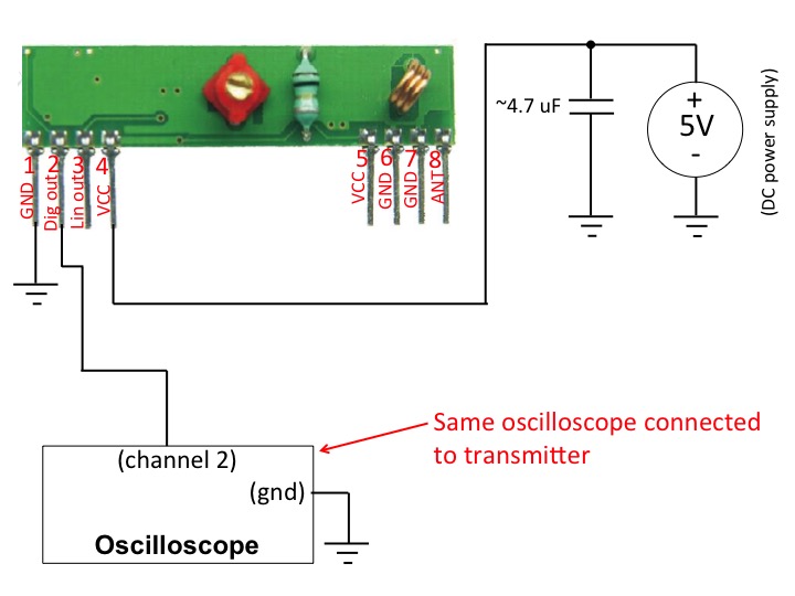
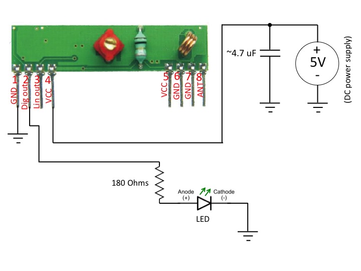
Connect the RF link transmitter module as shown in the measurement setup
diagram in Figure 1 using a solderless breadboard. If
you do not have a 9V battery, you can use a DC power supply. Make sure to not
connect the 9V battery (or turn on
the power supply) until you are sure all the other connections are
correct. The bypass/decoupling 4.7 uF capacitor
should be physically connected near the RF transmitter board to be most effective.
Once everything is in place, you may power the transmitter and
turn on the function generator. Note that antenna pin 4 is left open (you may connect
it to an unused row of pins on the breadboard). Even without an external antenna, the transmitter
will still radiate enough energy to be easily picked up by a receiver at short range.
Figure 1. Block diagram of the transmitter measurement setup
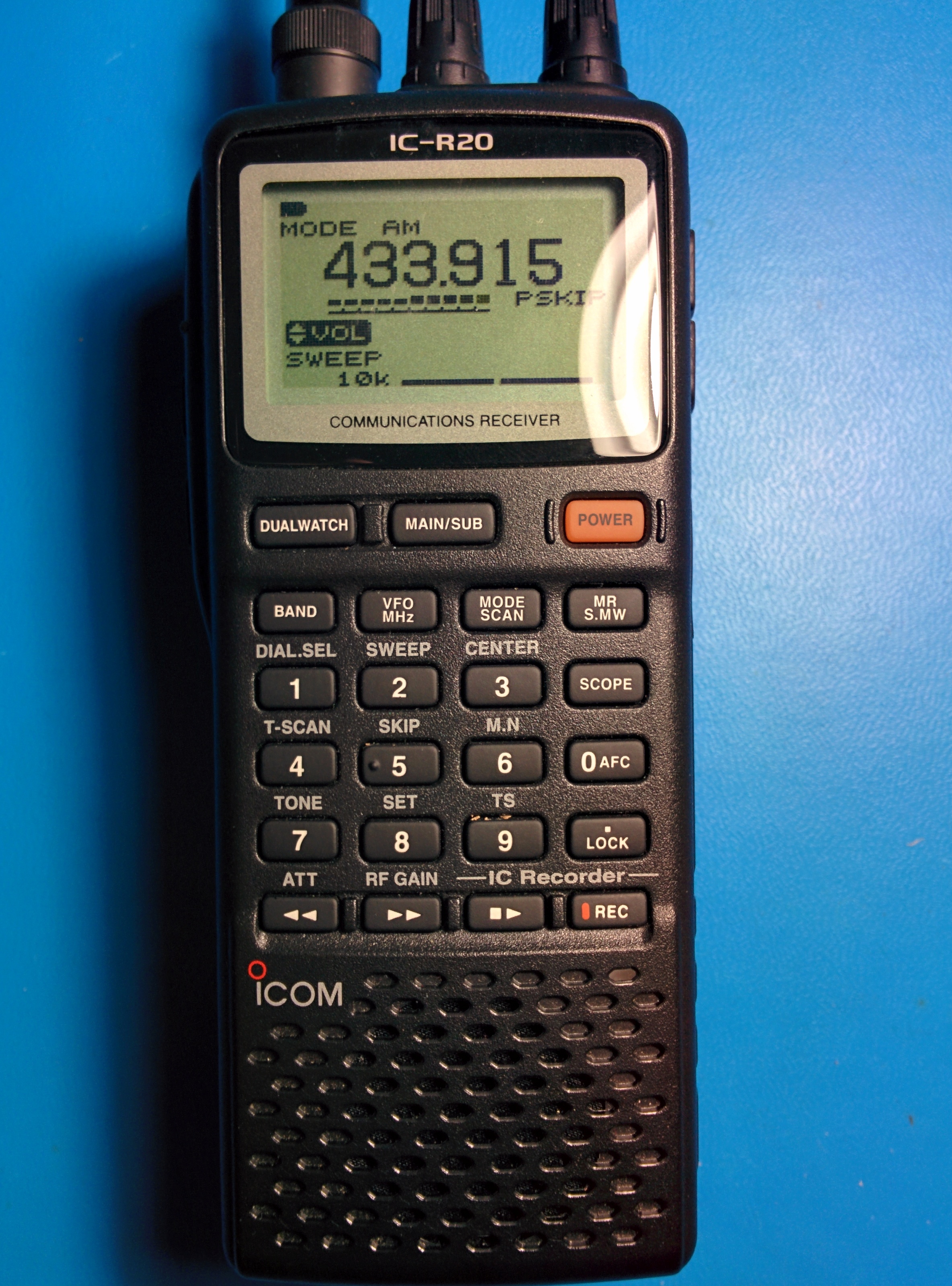
Use a handheld radio receiver, like the Icom IC-R20 (datasheet)
shown in Figure 2 to receive, demodulate, and listen to your transmitted signal.
Set the mode to AM. For the IC-R20 this is accomplished by pressing the "mode" button a few times until MODE AM is displayed on
the screen.
Many radios, like the Icom IC-R20 have a "band" button you can press to conveniently select the desired frequency band.
Once the proper frequency band is selected you can rotate the R-dial knob to fine tune the
receiver to the desired frequency (around 433.9 MHz.) You should be able to pick up and hear a 1 kHz tone.
Figure 2. Photograph of the Icom IC-R20 receiver.
Experiment with changing the mode on the receiver to
other options besides AM (i.e., change the mode to LSB, USB, CW, FM, and WFM).
With which modes can you hear and not hear the signal, and how do the different modes tonally
affect the received signal?
Present your answers in Slide 7.
Go back to AM mode.
Now change the frequency on the function generator lower and higher. You should be able to
hear this change on the receiver. Experiment with changing the duty cycle and wave type (
square, saw tooth, etc.) on the function generator. How do these changes tonally affect the received signal that you hear?
Report some
of your observations in Slide 8.
Take a walk with the receiver.
Can you still pick up the signal in another room? down the hall? from outside?
How far can you walk while still being able to pick up the signal?
Report your observations in Slide 9.
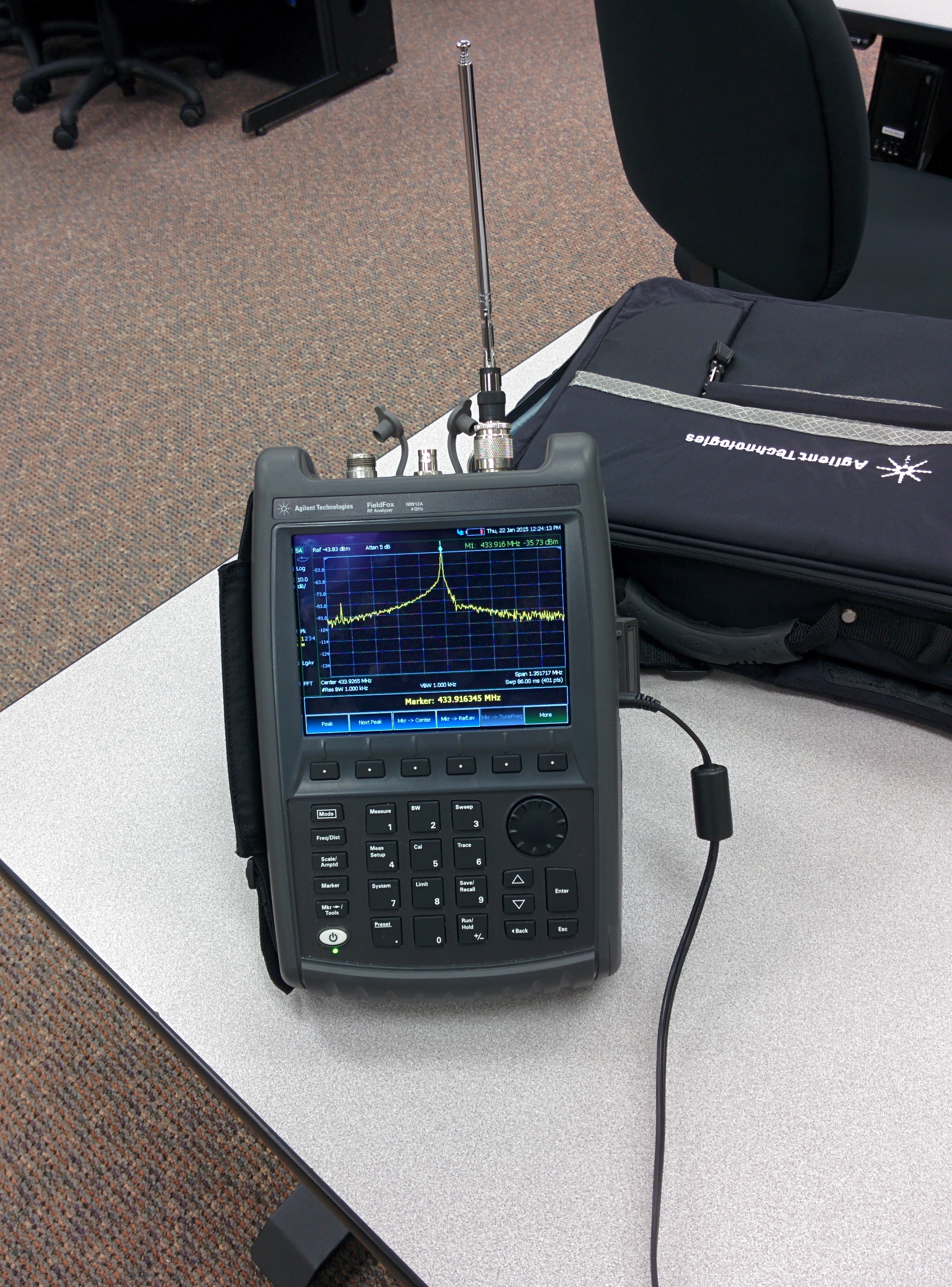
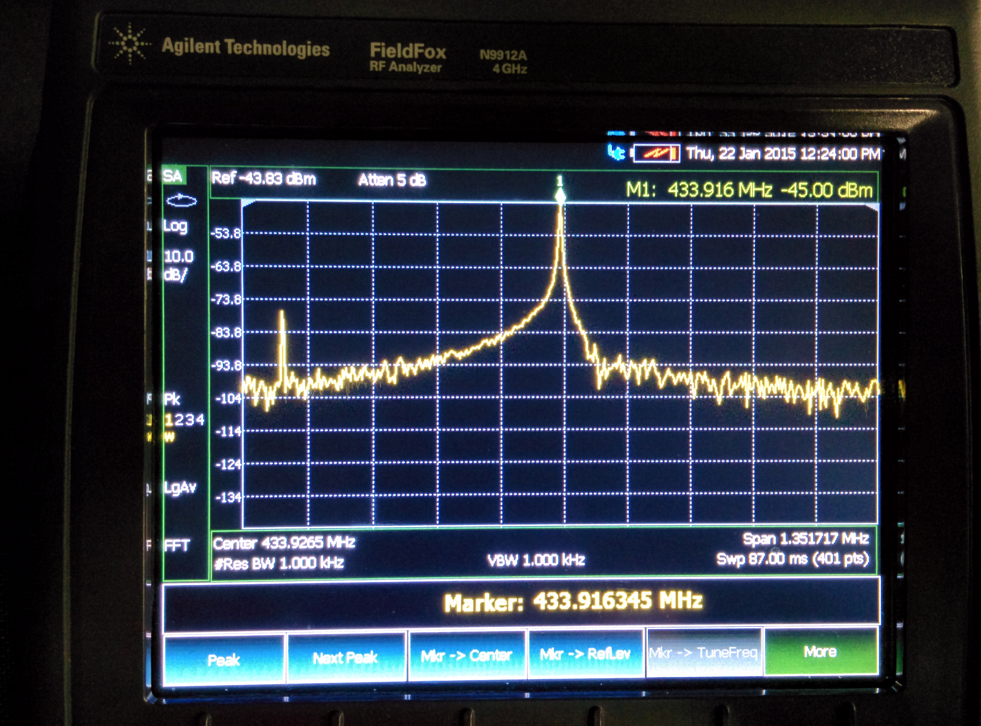
Connect an external antenna to a spectrum analyzer, and measure the frequency content of
the signal. A photograph of such spectrum analyzer making such a measurement is shown in Figure 3, and a screenshot of the
spectrum analyzer zoomed in on the signal is shown
in Figure 4.
When making your measurements, include a screenshot of the
spectrum analyzer and any interesting findings in
Slide 10. Your screenshot should be similar to that shown in Figure 4.
Cut a short hookup wire to be about a quarter-wavelength long (you calculated a wavelength
in Slide 3) and connect the wire to antenna pin 4, so that it's stranding straight up from the breadboard.
Does the short wire act to increase
the received signal measured by the spectrum analyzer compared to the case with no wire?
Try experimenting with different length wires for antennas. Is there an optimal length?
Report your findings in Slide 11. For this section keep in mind
that the inter-wire capactitance of the breadboard is going to have a big effect on the performance
of the antenna, so take your results with a grain of salt.
Figure 3. Photograph of spectrum analyzer making measurement
Figure 4. Screenshot of spectrum analyzer
RF link receiver setup and measurement
Keep the original RF link transmitter connected as before. On a second breadboard,
connect the RF link receiver module as shown in Figure 5. Make sure to wire the receiver on its own,
separate breadboard so that you can physically move it apart from the RF link transmitter. Feel free
to use a small (~13 cm) wire for an external antenna. However, an external antenna is not needed.
Figure 5. Block diagram of the receiver measurement setup
Make sure the function generator (which is connected to the RF link transmitter)
is generating a 1 kHz square wave with a 50% duty cycle. Move the receiver and transmitter a few feet from each other.
you should observe with the oscilloscope
a 1 kHz square wave on the digital output of the RF link receiver.
Increase the frequency of the function generator beyond 1 kHz.
What is the maximum frequency possible for the receiver to
reliably detect a square wave? How many bits per second does this correspond to?
How does this correspond to the published data rate on the receiver's spec sheet?
Present your answers in Slide 12.
Move the receiver and transmitter across the room and/or put obstacles between them.
Now what the maximum frequency possible for the receiver to reliably detect a square wave?
Present your answers in
Slide 13.
Disconnect the oscilloscope from the the RF link receiver, and connect an LED to the digital output
as shown in Figure 6. Change the frequency of the function generator (that is connected to the transmitter)
to a low frequency (around 3 Hz)
so that you can see the LED flashing. Take a picture of your receiver setup with LED and present
your picture in Slide 14
Figure 6. Block diagram of the reciever with LED
Conclusions
In slides 15 and 16, present your conclusions, summary and any extra information you would like to present for this lab.
In these slides you can include additional tables or plots or comments. For example, did you learn anything interesting in this lab?
Did you have any particular issues or challenges that you met? How did you meet them, etc.?
How do the RF links work?
The RF transmitter is a simple single-transistor AM modulator/oscillator, which uses a R433A
surface-acoustic wave (SAW) resonator for frequency stabilization. The RF receiver is a
super regenerative receiver involving a couple op amps, a couple transistors, and some
passive components. A link describing these circuits is found here.