To measure the self-capacitance and self-inductance of a simple two-wire transmission line. To illustrate how wire-spacing and
the environment effects these parameters. To measure the self-capacitance and self-inductance of a coaxial cable transmission line
2. Equipment
Two lengths of wire that each about three feet long. When preparing this lab and writing up these lab instructions, I used Elenco 22 gauge solid hookup wire, which worked well.
LCR meter used to measure inductance, capacitance, and resistance. In the pictures below I use an inexpensive hobby-level LC 100 A meter (for demonstration purposes).
You will perform your measurements with a higher-end meter such as a Keysight U1733C LCR Meter (or equivalent).
Wooden boards, non-metallic table, or other flat non-conducting structure to secure wires to.
Scotch tape to temporarily hold wires.
Wire strippers and cutters.
Ruler or measuring tape.
A few small alligator clips and extra wire to temporarily connect two wires together without the need to solder.
One 50 Ohm coaxial cable (roughly three feet long) with BNC male connectors on both ends.
One BNC female to double banana plug (see picture here)
One BNC female terminator with short circuit. For this experiment I use a bulkhead jack chassis mount with a small wire soldered to short the center conductor to ground (see picture here)
One BNC male to male adapter.
3. Report guidelines
For the lab report, you will create a PowerPoint presentation (or use a similar presentation program), save it as a PDF, and
submit it on-line according to the instructions given in class.
Your presentation (saved as a PDF) will have 11 slides, as asked for in the lab instructions.
If you miss a slide, please leave a blank slide in its place so that you still have exactly 11 slides total.
Please include a slide number in the footer of each slide.
Your first slide should be:
Slide 1: Title slide with your name (on top), names of your teammates (if you are working in a team), student ID number, date, lab number, class number/title.
4. Procedure
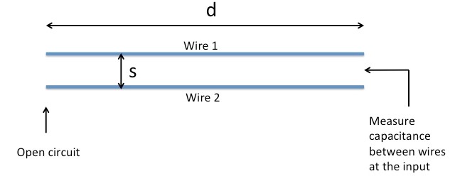
Measure capacitance and inductance of a two-wire parallel transmission line
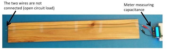
Place two equal lengths of wire (each approximate three-feet long) flat on a non-metallic table (or wooden board) such that the
wires are parallel and spaced 2.5 cm apart (about one inch). Measure the length of the transmission line, and present the length (in meters) in Slide 2. You will need this value later.
Set up the LCR meter to measure capacitance.
With the meter's test leads open (i.e., not connected to the transmission line), you will likely find that the meter measures a non-zero capacitance.
This is due largely to the capacitance between the leads themselves. To null out this effect, keep the test leads open and press the "null" or "zero" button on the meter.
The capacitance reading should now display zero (or at least display a very small value).
When the unit is zeroed by pressing the "null" or "zero" button, the unit stores the value of the capacitance and subtracts it from subsequent measured values. In our case,
this removes excess capacitance contributed by leads of the LC meter, which yields the "true" or "calibrated" capacitance of the coaxial line.
If your meter does not have a "null" or "zero" button, then record the value of capacitance when the meter's leads are open.
You will need to later manually subtract this value from the measured value of the capacitance of the line.
Copy and paste (or recreate) Table 1 (see below) in Slide 3. Currently, the table values are empty; you will update this table with your measured values as you work through this lab activity and present the completed table in slide 3.
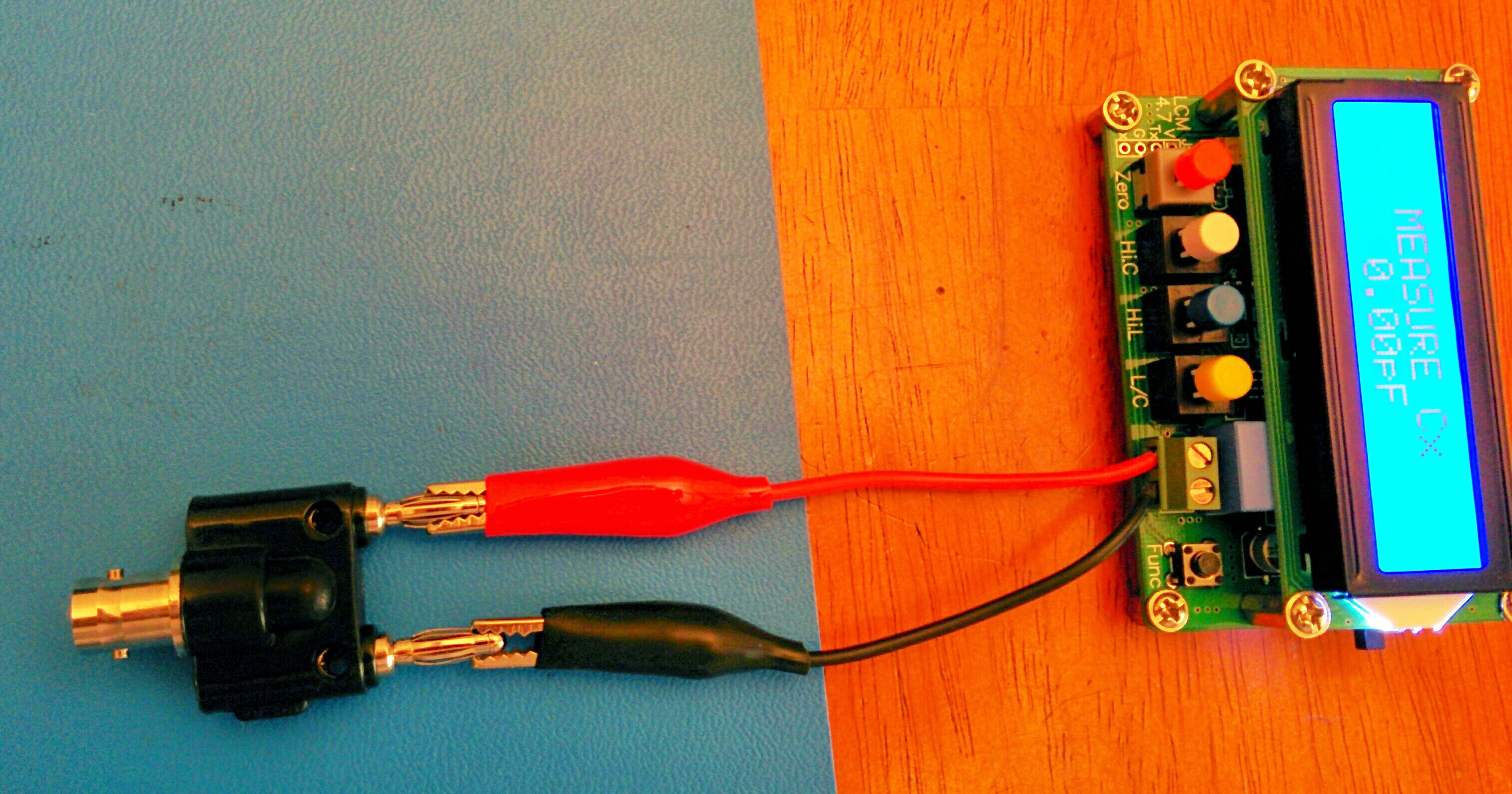
Connect the meter's test leads to one end of your two-wire transmission line, as illustrated in Figures 1 and 2. Measure the capacitance in pF of the two wire line, with the wires spaced 2.5 cm apart. The capacitance should be around 5 to 25 pF, depending
on the exact length of wires, how they are positioned, and the dielectric properties of the wooden board and/or table top.
Fill in the appropriate cell in Table 1 (slide 3) with this value.
Without disturbing or touching the wires, place your hand in different positions near the transmission line (such as between the two wires, or hovering your hand closely above the two wires).
Does your hand effect the value of the measured capacitance? How so?
Present our observations for this step in Slide 4.
With the wire-to-wire spacing still set to 2.5 cm, disconnect the LCR meter and set up the meter to measure inductance.
With the meter's test leads shorted together (which forms a small wire loop), you will likely find that the meter measures a non-zero inductance.
This is due largely to the inductance between the leads themselves. To null out this effect, keep the test leads shorted and press the "null" or "zero" button on the meter.
The inductance reading should now display zero (or at least display a very small value).
Reconnect the LCR meter (now set up to measure inductance) to the transmission line and short the far end of the line (as illustrated in Figures 4 and 5).
Measure the inductance in nH of the two wire line.
Fill in the appropriate box in Table 1 (slide 3) with this value.
Without disturbing or touching the wires, place your hand in different positions near the transmission line (such as between the two wires, or hovering your hand closely above the two wires).
Does your hand effect the value of the measured inductance? How so?
Present our observations for this step in Slide 5.
Vary the spacing between wires and fill out the capacitance and inductance columns, labeled "C [pF] and "L [nH]", respectively, in Table 1.
Next fill out the capacitance and inductance per unit length columns, labeled "C [F/mn] and "L [H/m]", respectively.
These per-unit-length values are easily calculated by dividing by the measured capacitance and inductance values by the measured length of the line.
The characteristic impedance is Z0= sqrt(L/C) and the phase velocity is vp = 1/sqrt(L*C),
where for both equations L is the inductance in [H] and C is the capacitance in [F].
The velocity factor VF = vp/c0, where c0 is the speed of light.
With these equations, fill out the remaining two columns of Table 1 (slide 3). Note that, since the phase velocity should be less than the speed of light (vp < c),
we expect VF < 1.
In Slide 6 present and discuss how your measured results compare with the line parameters (inductance, capacitance, characteristic impedance, and phase velocity) of an ideal twin wire transmission line suspended in vacuum.
For calculating the inductance of the ideal line, you can use Clemson University's Twin Wire Inductance Calculator.
Once you have inductance, you can calculate the capacitance of an ideal transmission line using the basic equation: 1/sqrt(LC)=c0, where c0 is the speed of light.
Table 1: Measured results for two-wire transmission line (Table created using Tables Generator).
Spacing [cm]
C [pF]
L [nH]
C/length [F/m]
l/length [H/m]
Z0 [Ohms]
VF (velocity factor)
.5
___________
____________
2.5
5
7.5
10
Figure 1. Setup for measuring self-capacitance of two-wire transmission line.Figure 2. Photograph of the setup for measuring self-capacitance of two-wire transmission line.
Measuring Self-Inductance and Self-Capacitance of a Coaxial Cable
In this section you will measure the self-capacitance and self-inductance of a coaxial cable using similar methods to those you used to measure the two-wire transmission line
(i.e. by opening and shorting the load end, respectively). H
Connect the BNC-female-to-double-banana plug (without the cable) to the LC meter as shown in Figure 3. Set the meter to measure capacitance.
If your meter has a "null" or "zero" button, press it to zero the unit by
removing excess capacitance contributed by the adapter and leads of the LC meter.
If your meter does not have a "null" or "zero" button, then record the value of capacitance when the meter is connected to just the adapter alone.
You will need to later manually subtract this value from the measured value of the capacitance of the line.
Figure 3. BNC-female-to-double-banana plug adaptor connected to LC meter.
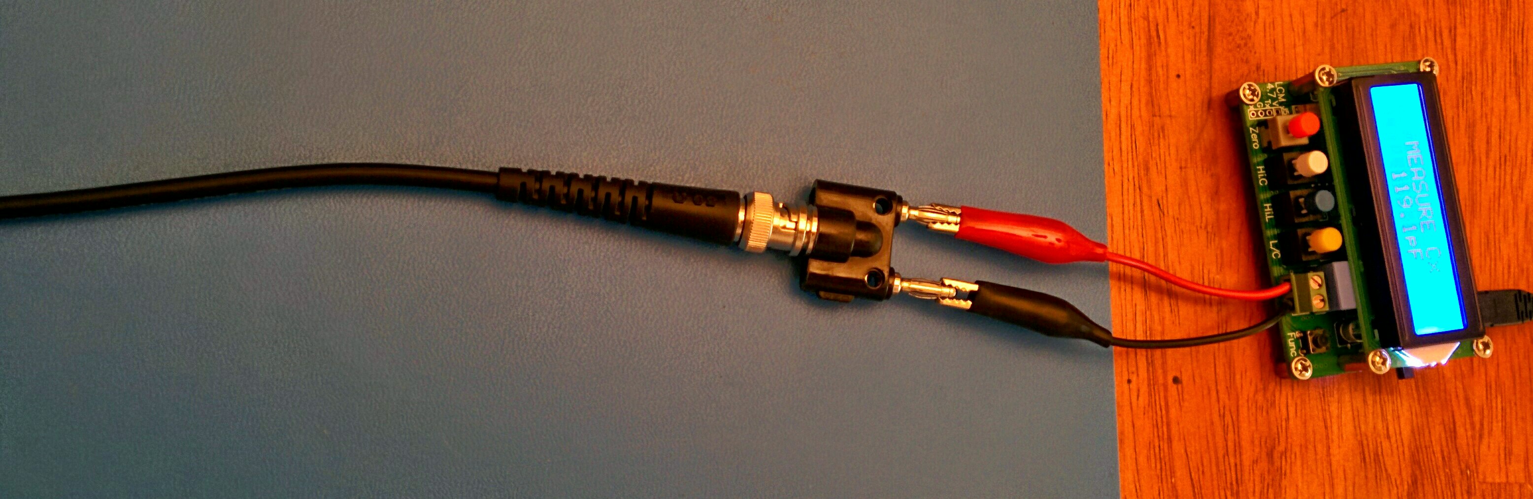
Connect the coaxial cable to the LC meter via the BNC-female-to-double-banana plug adaptor, as shown in Figure 4. Make sure the cable is positioned straight (not bent),
measure the capacitance,
and fill out the appropriate columns in Table 2 with your results. Present this table in Slide 7.
Does placing your hand on the cable or bending the cable change the capacitance? Present your observations in Slide 8.
Figure 4. Coaxial cable connected to LC meter via BNC female to double banana plug adaptor.
Table 2: Measured results for coaxial cable
C [pF]
L [nH]
C/length [F/m]
l/length [H/m]
Z0 [Ohms]
VF (velocity factor)
___________
___________
Set the LC meter to measure the inductance of the coaxial cable.
When making the inductance measurement, short out the end of the cable using the BNC female terminator with short circuit (see the Equipment List.)
Before making the inductance measurement, note that the adaptors and the short circuit contribute additional inductance to the measurements that needs to be "calibrated out".
To do this, set the LCR meter to measure inductance and disconnect the BNC adapter from the coaxial cable, so that the measurement setup resembles that shown in Figure 3.
Next, short out the BNC connector using a BNC terminator with short circuit. Then press the "zero" or "null" button.
Now perform the inductance measurement of the coaxial cable, and fill out Table 2 with your results.
Does placing your hand on the cable or bending the cable change the inductance? Present your observations in Slide 9.
Now that you you have both capacitance and inductance measurements, fill out the rest of Table 2.
The characteristic impedance is Z0 = sqrt(L/C) and the phase velocity is vp = 1/sqrt(L*C), where for both equations L is the inductance per meter in [H/m] and C is the capacitance per meter in [F/m].
The phase velocity should be less than the speed of light (but on the same order of magnitude as the speed of light). Hence the
velocity factor VF < 1.
On the side of the coaxial cable should be written the characteristic impedance (for this experiment the characteristic impedance should be 50 Ohms).
In Slide10 discuss how well the characteristic impedance you measured (indirectly from L and C) compares with this ideal value.
Present your conclusions, summary of what you learned, and how you can apply what you learned to your engineering
practice in Slide 11.
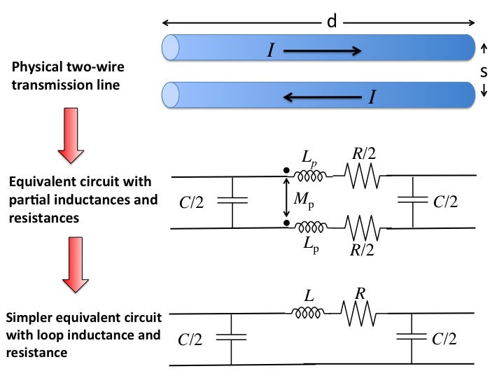
5. Equivalent circuit model and theory
A good model (equivalent circuit) of a small segment of two-wire transmission line is shown in the figure below. Here, we define "small"
as "electrically small", meaning the length of the line is significantly smaller than a guide wavelength. In this manner, we can
safely ignore standing waves on the line, and model the line with discrete lumped elements.
In the model, the transmission line is described by the lines self-capacitance (C), self-inductance (L), and resistance (R). Note that this model ignore
any dielectric leakage between the two wires, which is usually relatively small anyway.
The parameters R,L, and C depend on the physical dimensions and materials of the transmission line. For example, when you double the length of the line,
the values for R,L, and C double. When you increase the spacing between the conductors,
the inductance L increases while the capacitance C decreases.
Figure 6. Two-wire transmission line equivalent circuit.
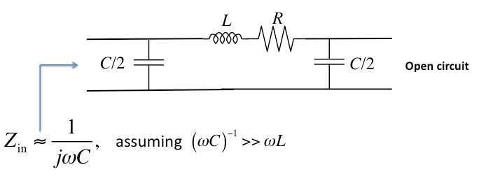
To measure the self-capacitance of the electrically-short transmission line, we open one end of the line and measure the capacitance from
the other end. As illustrated in the figure below, with one end open, the voltage drop accross the inductor is much smaller than
that across the capacitors, and the circuit's behaviour is dominated by its self-capacitance.
Figure 6. Two-wire transmission line equivalent circuit: measuring self-capacitance.
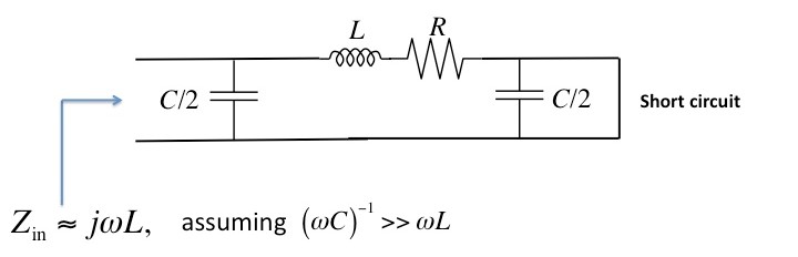
To measure the self-inductance of the electrically-short transmission line, we short one end of the line and measure the inductance from
the other end. As illustrated in the figure below, with one end short, the currents through the capacitors are very small, and the circuit's
behaviour is dominated by its self-inductance.
Figure 7. Two-wire transmission line equivalent circuit: measuring self-inductance.