GNU Radio Companion - BSPK Pulse shaping + channel + matched filter + timing sync

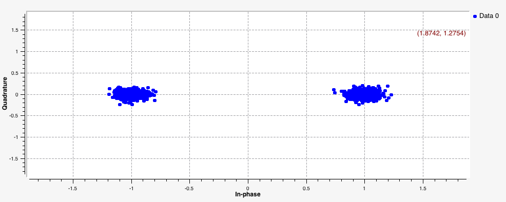
How to convert a digital data stream to a baseband analog signal using the built-in constellation modulator block, pass the data through a noisy channel, and then recover the original data stream using the polyphase clock sync block for matched filtering + timing recovery.

Prepared by Dr. Aaron Scher
[email protected]
Oregon Institute of Technology

Back to My collection of GNU radio companion flow graphs
Back to Aaron's home page.

(Last updated: Oct 2015)

Download file: BPSK_mod_demod.grc.

Flow Graph:

Description of flow graph (starting from the left and working our way right)

  1. A vector sources produces our digital data stream 1, 0, 1, 1, 0, ... (REPEAT). This digital data stream is a stream of bits (i.e., unpacked bytes with 1 relevant bit per byte).
  2. The bits are packed to create packed bytes (each packed byte caries 8 relavent bits).
  3. The flow of samples is placed through a throttle block so that the average rate does not exceed 100 kilo-samples per second. When there is no other rate limitting block (like in this simulation), it's good practice to include a throttle block. I decided somewhat randomly to put it here.
  4. The packed bytes are then sent to the constellation modulator block. This block performs the following operations.
  5. Our baseband signal is now passed through the channel model block. This models our analog transmission path. Here we can add noise and a frequency offset to our signal. The channel is modeled as finite-impulse response linear filter. Through the use of taps, we can shape its frequency response. Note that we are not actually upconverting our baseband signal with a carrier wave in this simulation. We are dealing with baseband transmission.
  6. Next the signal arrives at the the Polyphase Clock Sync block. The block first passes the signal through a matched SRRC filter. The block then iteratively estimates the instants at which to sample the resulting signal (based on the known sps parameter, and filter parameters like loop bandwidth, filter size, initial phase, and maximum rate deviation). It does this by implementing a particular maximum likelihood timing-recovering algorithm - the details of which can be found by searching for "Polyphase Clock Sync". In the end, assuming the block is functioning correctly (and assuming no channel attenuation or gain), it will output a sequence of numbers that are very close to the actual symbols that were originally sent. So if our original symbol stream is: +1, -1, +1, +1, -1, ..., then ideally the output of the Polyphase Clock Sync block will be +1, -1, +1, +1, -1, ... However, due to the block's own imperfections and channel effects (like noise), the output won't be exactly what we sent, but it should hopefully be something numerically similar, like +1.01+j0.001, -.99+j0.012, +1.13+j0.00, +.98-j0.12, -1.05-j0.02,... Note that this block downsamples the input signal by a factor sps. In a sense, this "undoes" the original upsampling performed by the constellation modulator. Time and constellation sinks are used to monitor the output of this block.
  7. The next block extracts the real part of the estimated symbol sequence. Then this data is passed to a binary slicer block. If the input to the binary slicer is less than 0, then the binary slicer outputs a 0 (unpacked byte). If the input to the binary slicer is greater than 0, then the binary slicer outputs a 1 (unpacked byte). We can't plot bytes using a time sink. So I convert the bytes to floating point values using the Chunks to Symbols block. In this manner, a 0 (unpacked byte) is converted to a 0 (floating point) and a 1 (unpacked byte) is converted to a 1 (floating point). Finally, a WX GUI Time Sink is used to monitor the output data sequence. This data sequence is what it's all about! It is the received binary signal (i.e.the output of the receiver). If all goes well, this received binary signal should equal the original transmitted data sequence, namely 1, 0, 1, 1, 0,... (REPEAT).

Output

Here are the outputs for a noise voltage equal to 0.1 V (no frequency or phase offsets).

Output of Polyphase Clock Sync (time plot and constellation diagram)

Mod/Demod

Output of binary slicer: Note that we recover our input data sequence! 1, 0, 1, 1, 0 (REPEAT)