Check out the great Wikipedia Joule Thief article.
Wikipedia describes the joule thief "a minimalist Armstrong
self-oscillating voltage booster that is small, low-cost, and easy to build,
typically used for driving light loads."
In this page, I am going to describe how the Joule Thief works.
Basic Principle 1. A battery, a switch, a couple resistors, and an inductor can generate a large voltage (much larger than the battery voltage itself).
In Figure 1 below, we see how continuously shorting and not-shorting out a resistor load RL can generate
a large voltage across the resistor. What's happening is that current through an inductor cannot change
instantaneously (this is because a magnetic field cannot "collapse" instantaneously). When the switch is
closed (i.e. the load resistor RL is shorted out) current increases until the current maxes out at I = Vdc/Rwire.
After this large current is developed, the switch is suddenly opened and the inductor is forced to push this current through
the load resistor RL, which generates a large voltage across RL (this is all because the current through an inductor cannot change
instantaneously). This large voltage only occurs for a short
time (i.e. we get a voltage pulse), and the current decays with a time constant L/(RL+Rwire) to
a new low value I = Vdc/(RL+Rwire). Then the switch is
closed again (shorting out RL) and the current rises to the max value I = Vdc/Rwire so that the whole process can begin anew.
Figure 2 shows a spice simulation of the simple switching network, which demonstrates the
generation of large voltage pules. Figure 3 shows the load resistor replaced by an LED.
Figures 4 and 5 show the ideal switched replaced by a BJT. When the voltage applied to the base of
the BJT is low (0V), the BJT is cut-off (C-E open circuited), and when the voltage applied ot the base of
the BJT is high (5V), the BJT is saturated (C-E short-circuited).
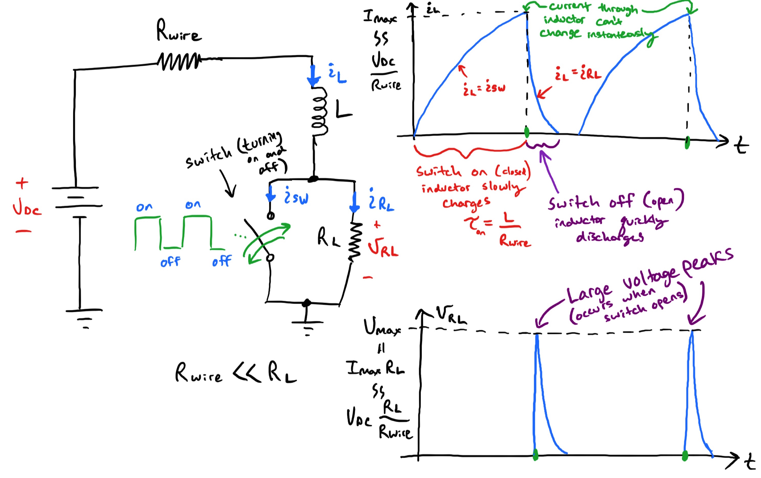 Figure 1. This image presents a main a main principle behind the operation of the
Joule Thief - A battery, a switch, a couple resistors, and an inductor can generate a large voltage (much larger than the battery voltage itself). Click to enlarge
Figure 2. Spice simulation of the simple switching network, which demonstrates the
generation of large voltage pules. (Click to enlarge)
Figure 3. Load resistor has been replaced by an LED. (Click to enlarge)
Figure 4. BJT can be used in place of an ideal switch. (Click to enlarge)
Figure 5. Spice simulation with switch replaced by a BJT (Click to enlarge)
Figure 1. This image presents a main a main principle behind the operation of the
Joule Thief - A battery, a switch, a couple resistors, and an inductor can generate a large voltage (much larger than the battery voltage itself). Click to enlarge
Figure 2. Spice simulation of the simple switching network, which demonstrates the
generation of large voltage pules. (Click to enlarge)
Figure 3. Load resistor has been replaced by an LED. (Click to enlarge)
Figure 4. BJT can be used in place of an ideal switch. (Click to enlarge)
Figure 5. Spice simulation with switch replaced by a BJT (Click to enlarge)
Basic Principle 2. The magnetic field generated by an inductor induces an EMF (voltage) in another inductor through mutual inductance (and vice versa)
The principle of mutual inductance is illustrated in Figure 6.
Figure 6. The magnetic field generated by an inductor induces an EMF (voltage) in another inductor through mutual inductance (and vice versa).
Putting it all together to form Joule Thief circuit
Figure 6 presents a Spice simulation of the Joule Thief circuit.
Figure 6.(Click to enlarge)
Figure 7.(Click to enlarge)
Figure 8.(Click to enlarge)