Circuit a day: coaxial cable
Prepared by Dr. Aaron Scher
[email protected]
Oregon Institute of Technology
Back to Aaron's home page.
Back to Circuit a day.
Prepared by Dr. Aaron Scher
[email protected]
Oregon Institute of Technology
Back to Aaron's home page.
Back to Circuit a day.
Our lumped-element model for the coaxial cable is shown in Figure 1. It is assumed that the cable is short compared to the wavelength. In this model, we consider the coax as composed of three separate conductors: (1) the center conductor, (2) the inner region of the shield conductor, and (3) the outer region of the shield conductor. Each of these three regions are characterized by a lumped inductance and a lumped resistance. All three regions are magnetically coupled together. A lumped capacitor models electric coupling between the center conductor and the shield. We assume the coaxial cable is above a ground plane. I admit that this lumped-element model can definitely be refined and improved at the cost of added complexity. For example, we know that current will flow near the outer surface of the inner conductor at high frequencies. This can be modeled by dividing up the inner conductor into multiple regions (like we did with the outer conductor).

The inductance per unit length of the three conductors are given by the following equations:
In the above equations, mu is the magnetic permeability of free space, h is the distance above the ground plane, di is the diameter of the center conductor, ds_inner is the diameter of the inner region of the shield, and ds_outer is the diameter of the outer region of the shield. The mutual inductances (per unit length) are given below:
Below I present a number of situations I simulated with LTspice to get an overall feel for the coaxial cable in terms of the cable's operation and electromagnetic compatibility (using the simple lumped element model presented in Figure 1). These simulations clearly show the effects of skin/proximity effects. Click on the picture below to see the simulation results and my comments.
Where do the currents flow in an isolated coax? Click on the pic below to find out!
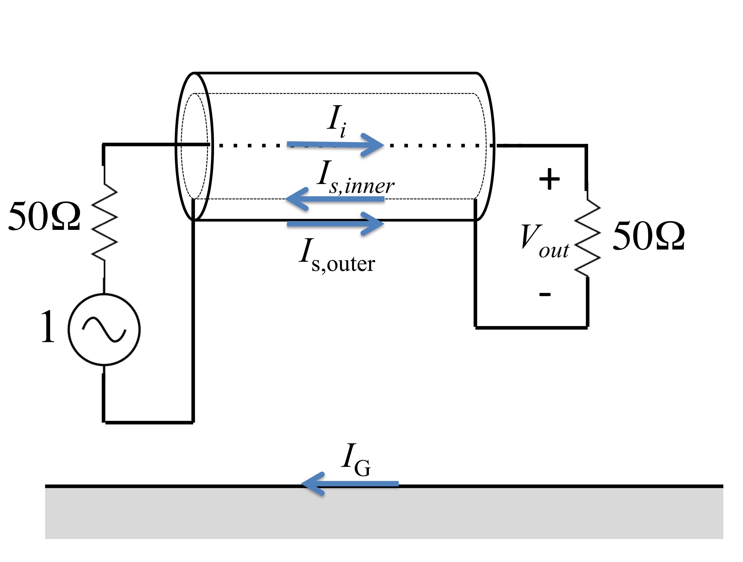
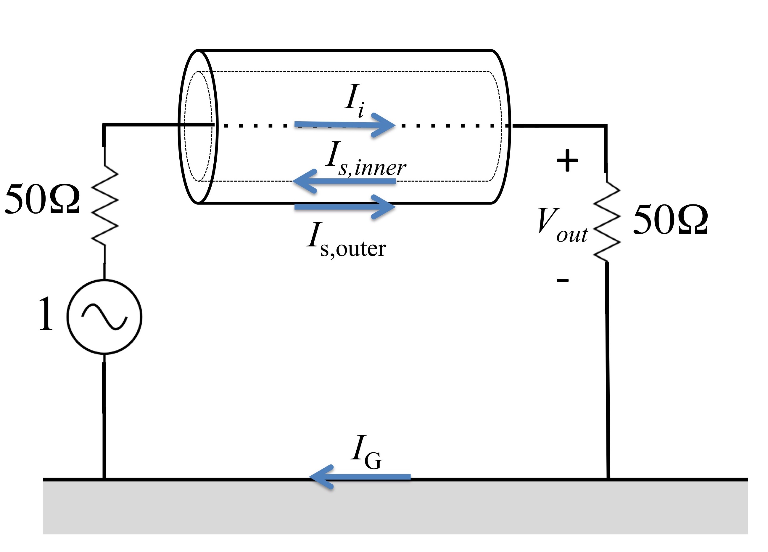
Where do the currents flow in a coax if the input and output terminals are grounded? Click on the pic below to find out!
Where do the currents flow in a shielded wire (with the shield "floating") connected to ground? Click on the pic below to find out!
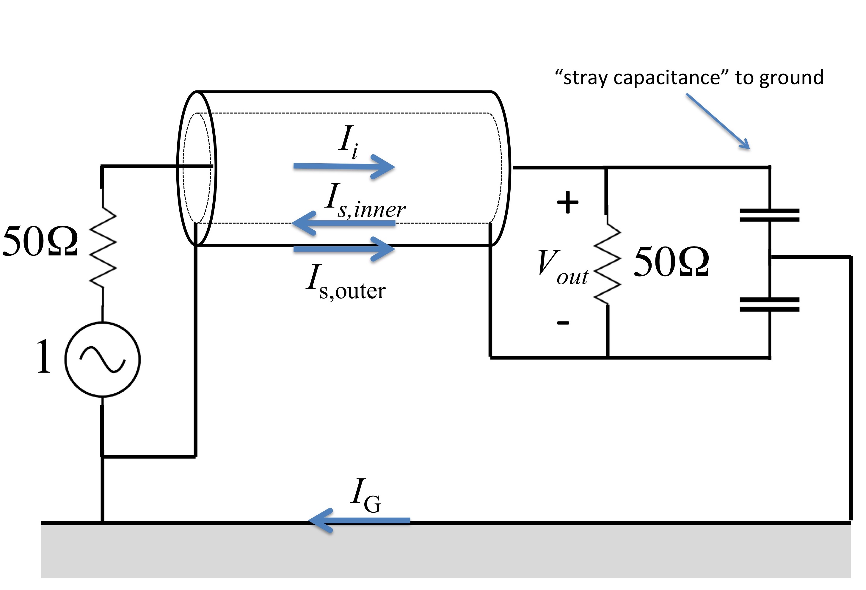
Where do the currents flow in a coax if there is some "stray capacitance" to ground? Click on the pic below to find out!
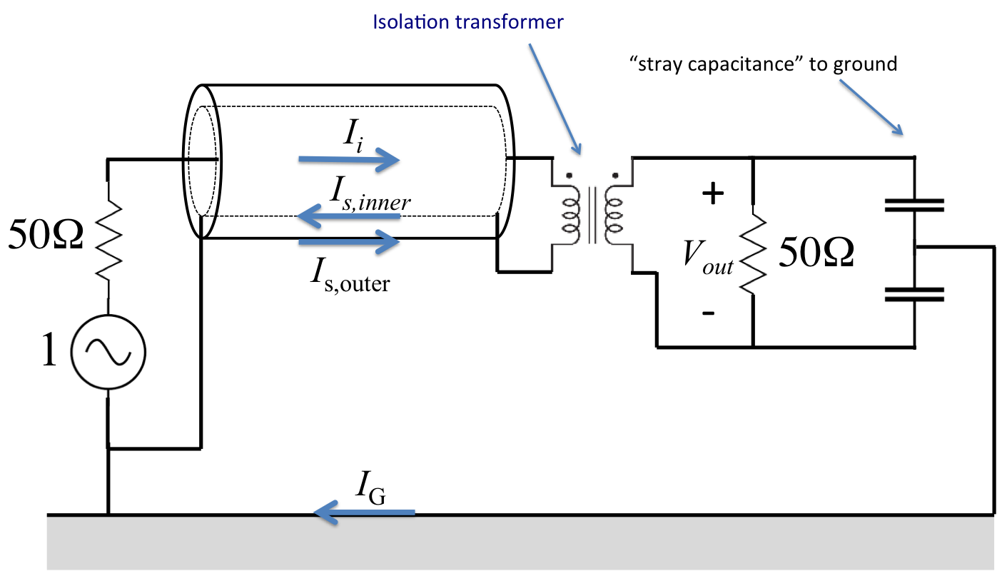
What happens if we use an isolation transformer to "combat" the effects of the "stray capacitance" to ground? Click on the pic below to find out!
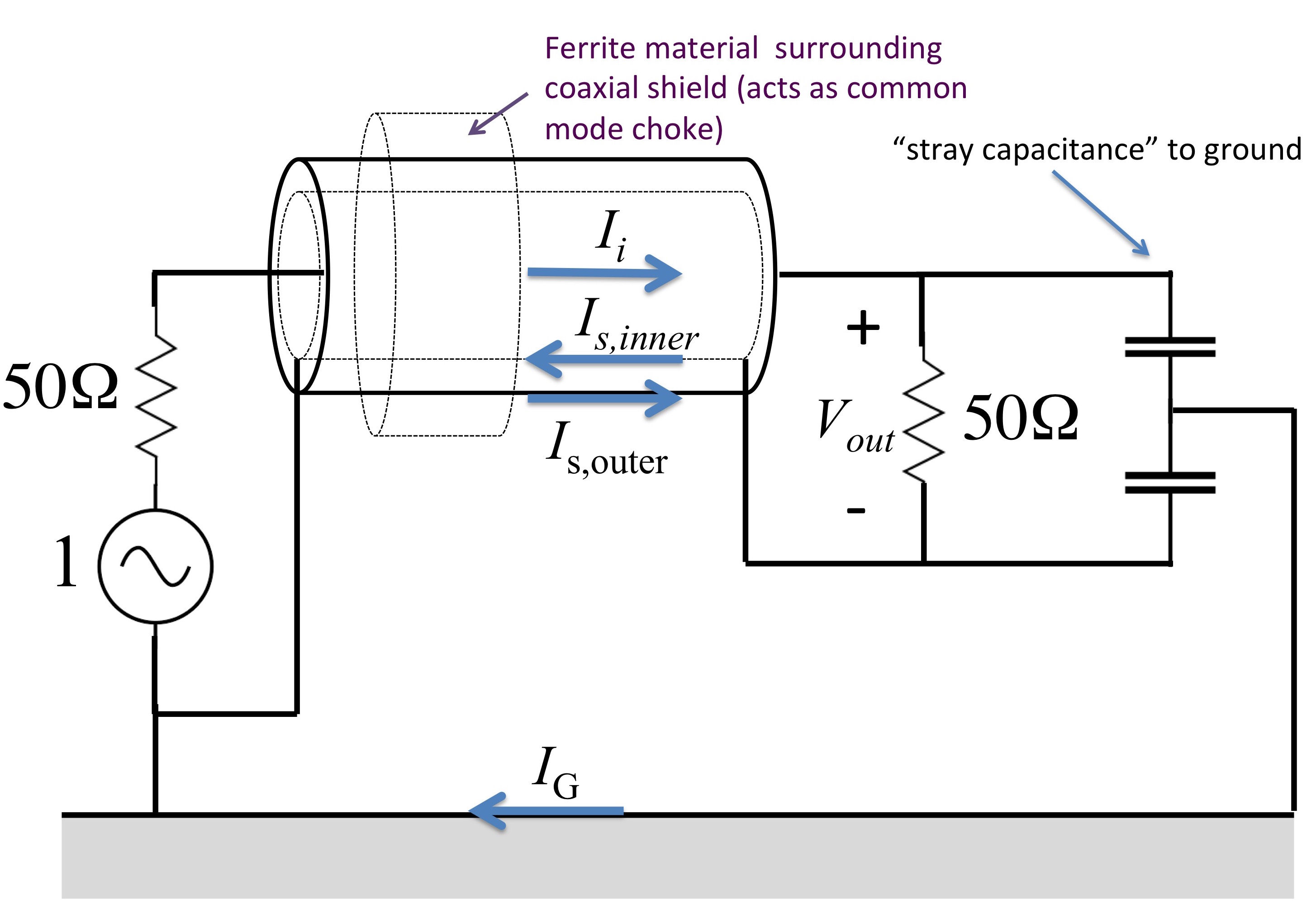
What happens if we use a ferrite common mode choke to combat the effects of the stray capacitance to ground? Click on the pic below to find out!
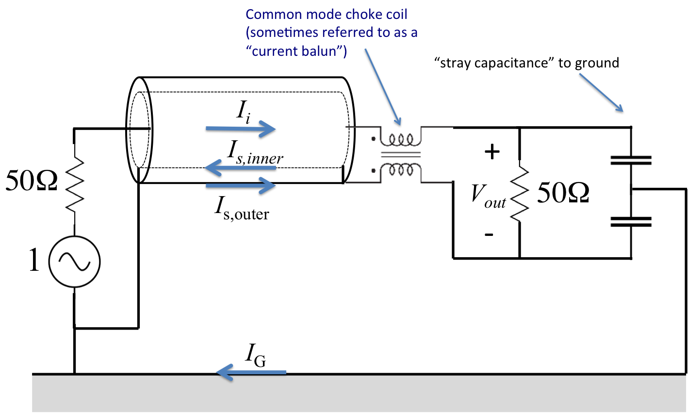
What happens if we use a common mode choke (sometimes called a "current balun") to combat the effects of the stray capacitance to ground? Click on the pic below to find out!
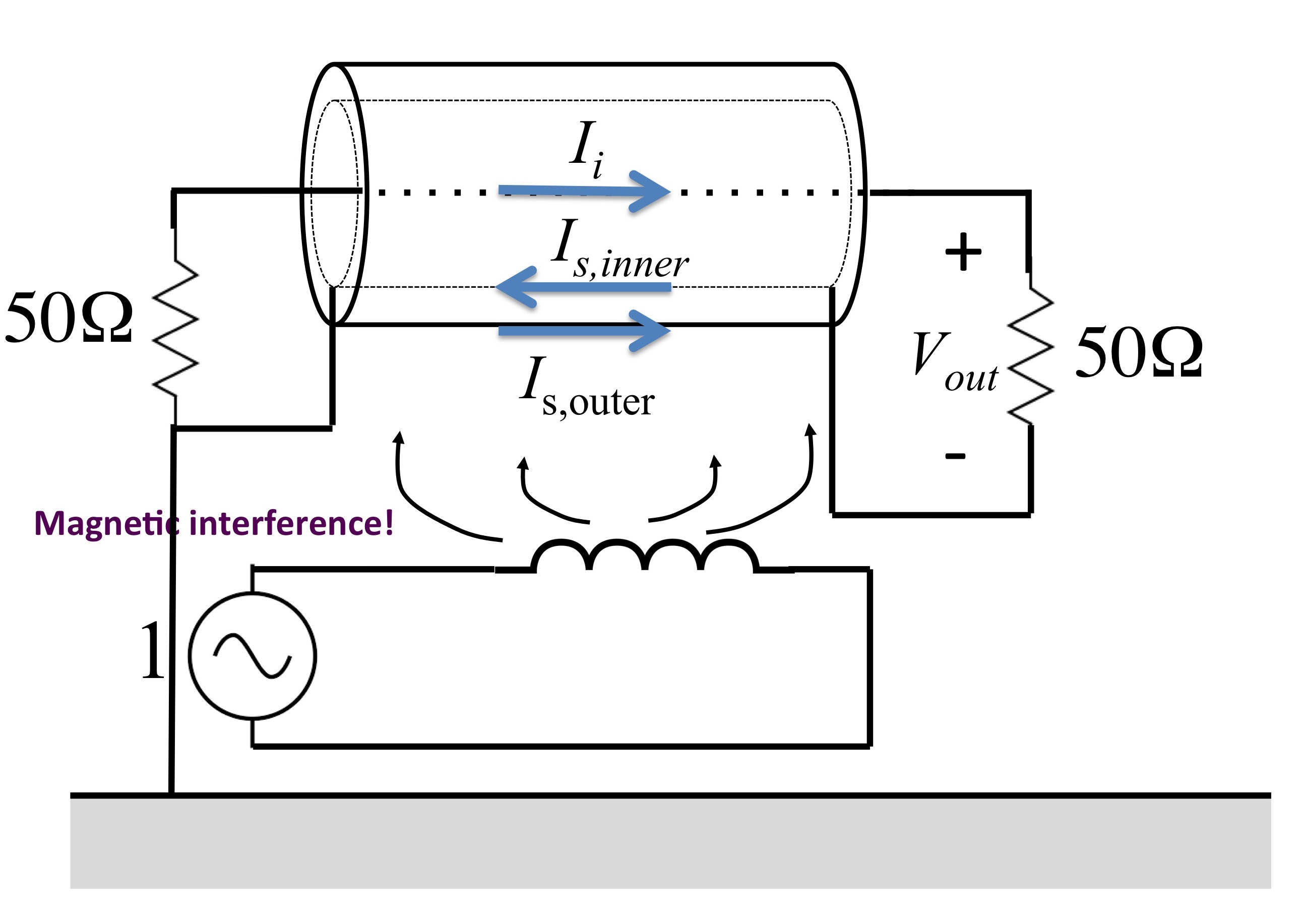
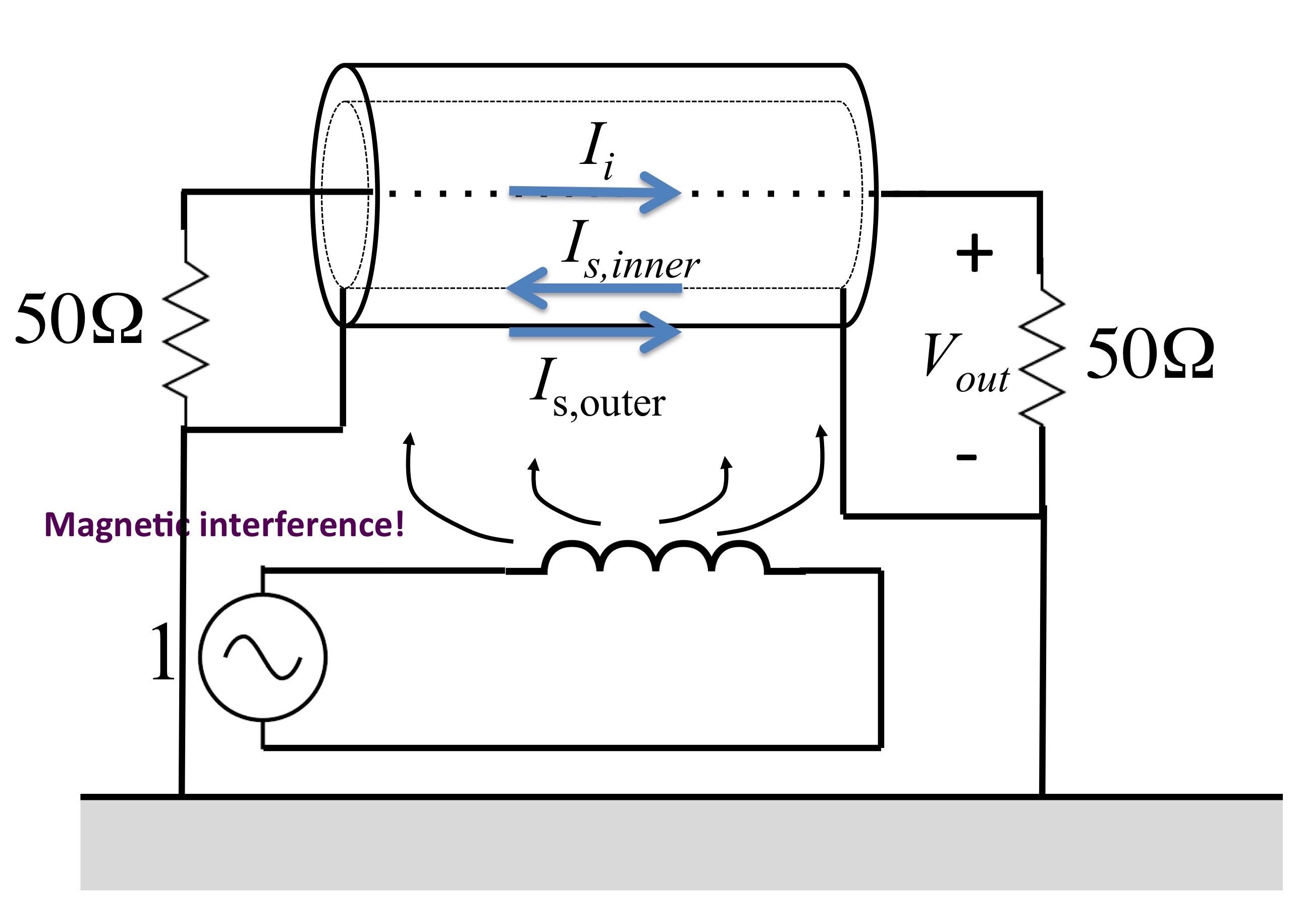
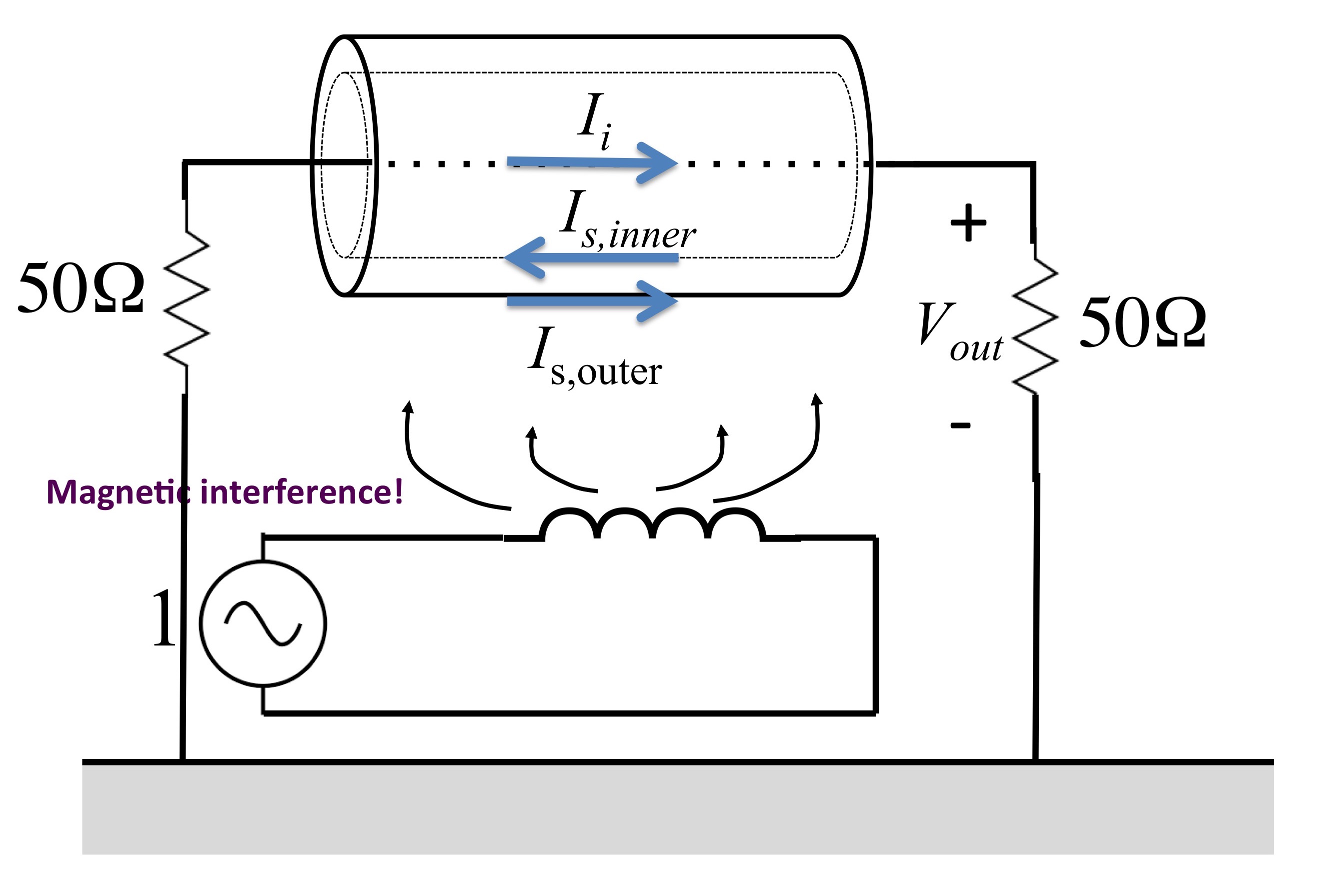
How does a coax grounded at one end react to magnetic interference? Click on the pic below to find out!
How does a coax grounded at both ends react to magnetic interference? Click on the pic below to find out!
How does a wire connected to ground with a floating "shield" around it react to magnetic interference? Click on the pic below to find out!
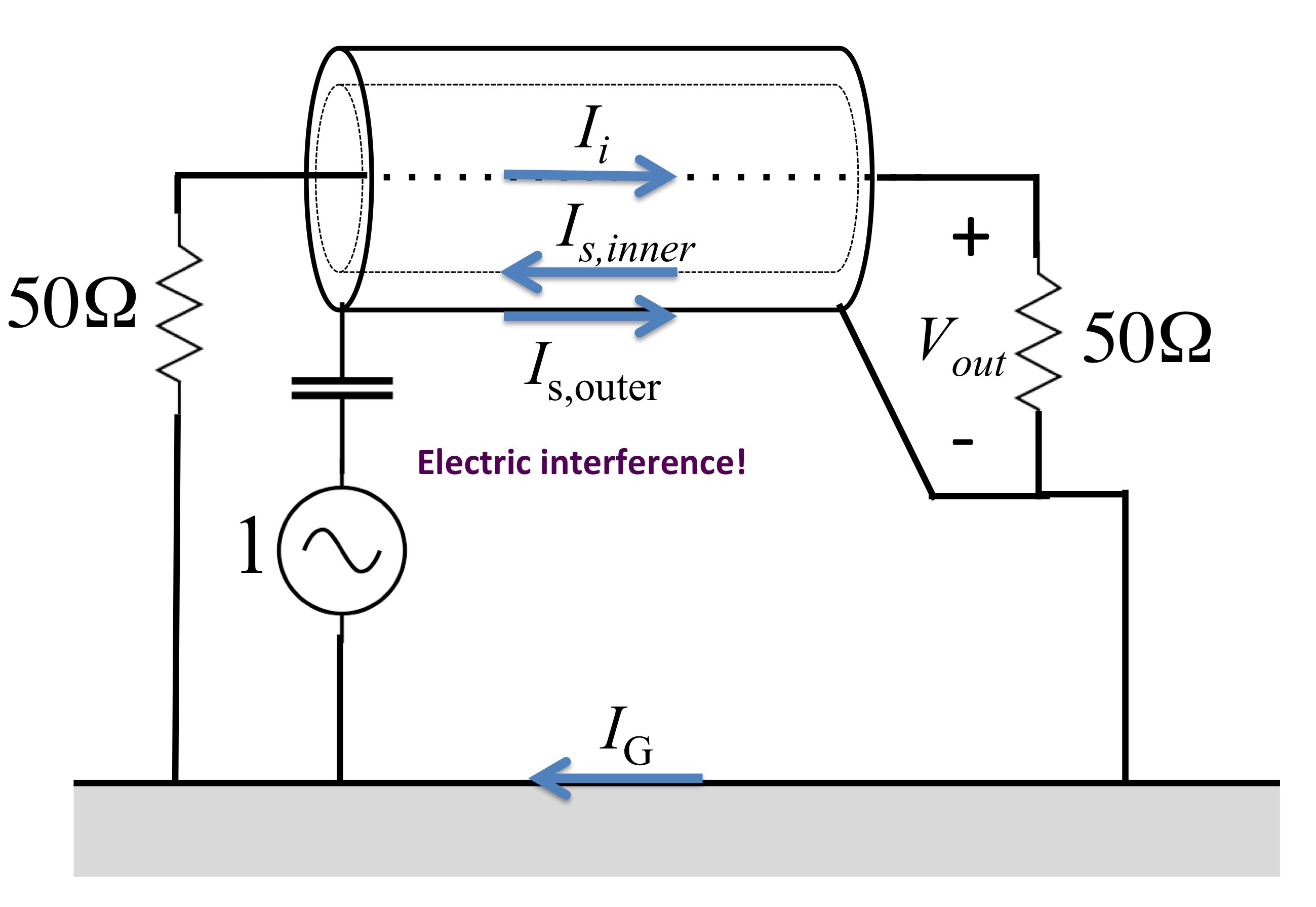
How does a wire connected to ground with a floating "shield" around it react to electric interference? Click on the pic below to find out!
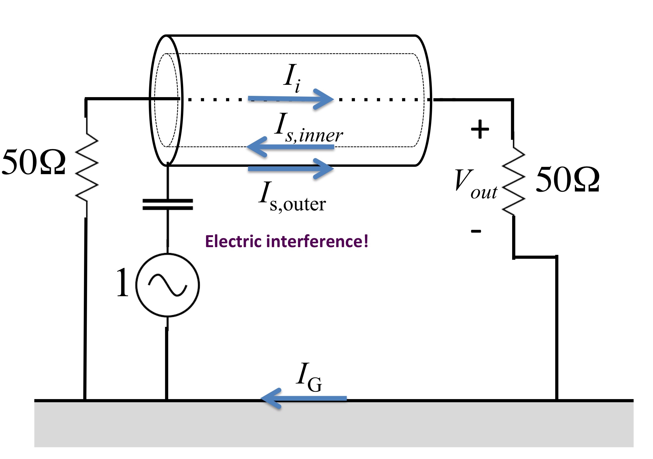
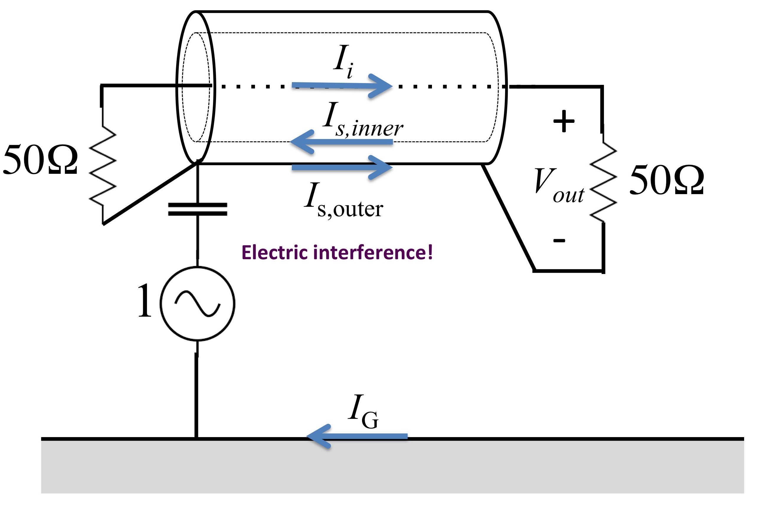
How does a wire connected to ground with a grounded "shield" around it react to electric interference? Click on the pic below to find out!
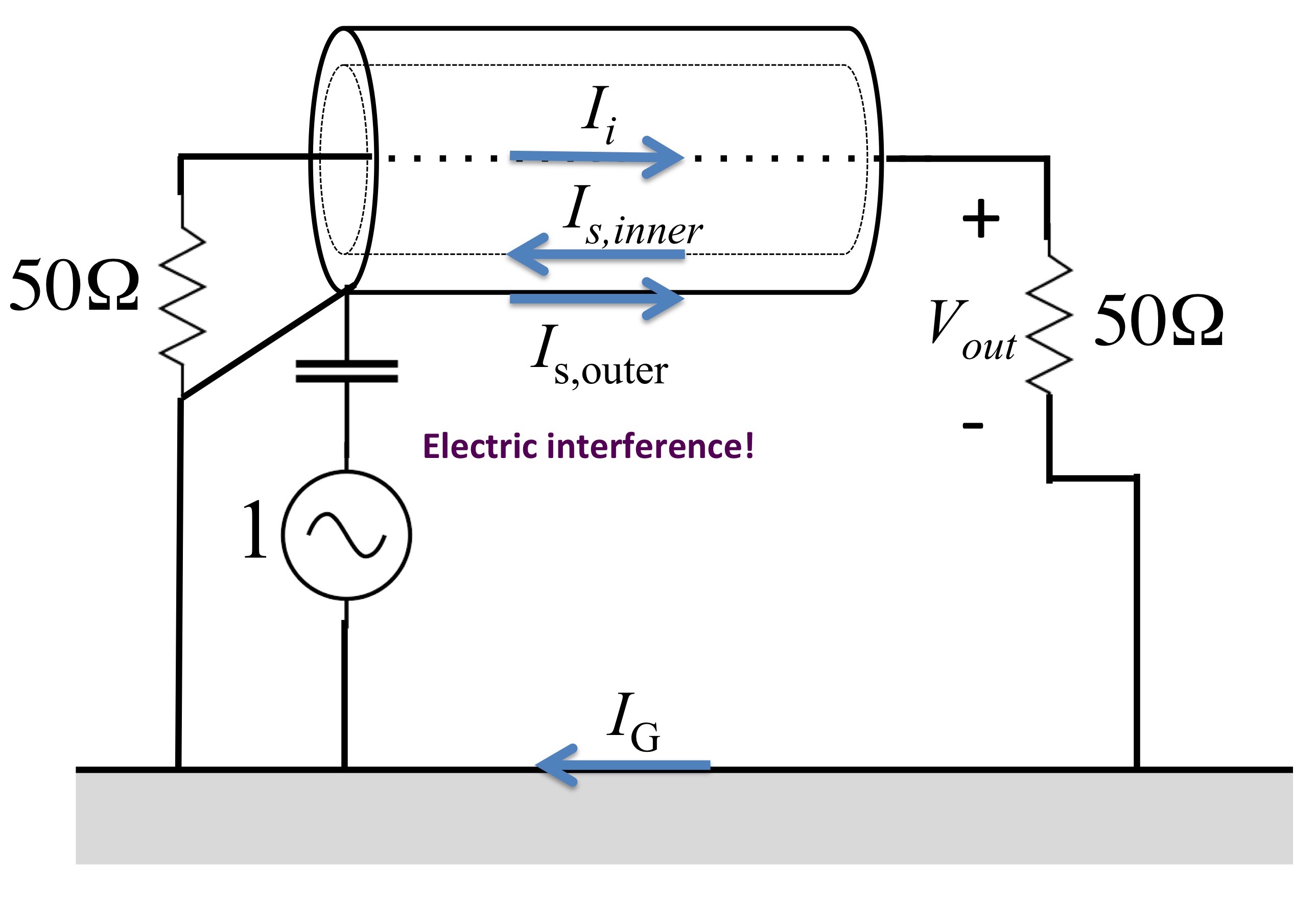
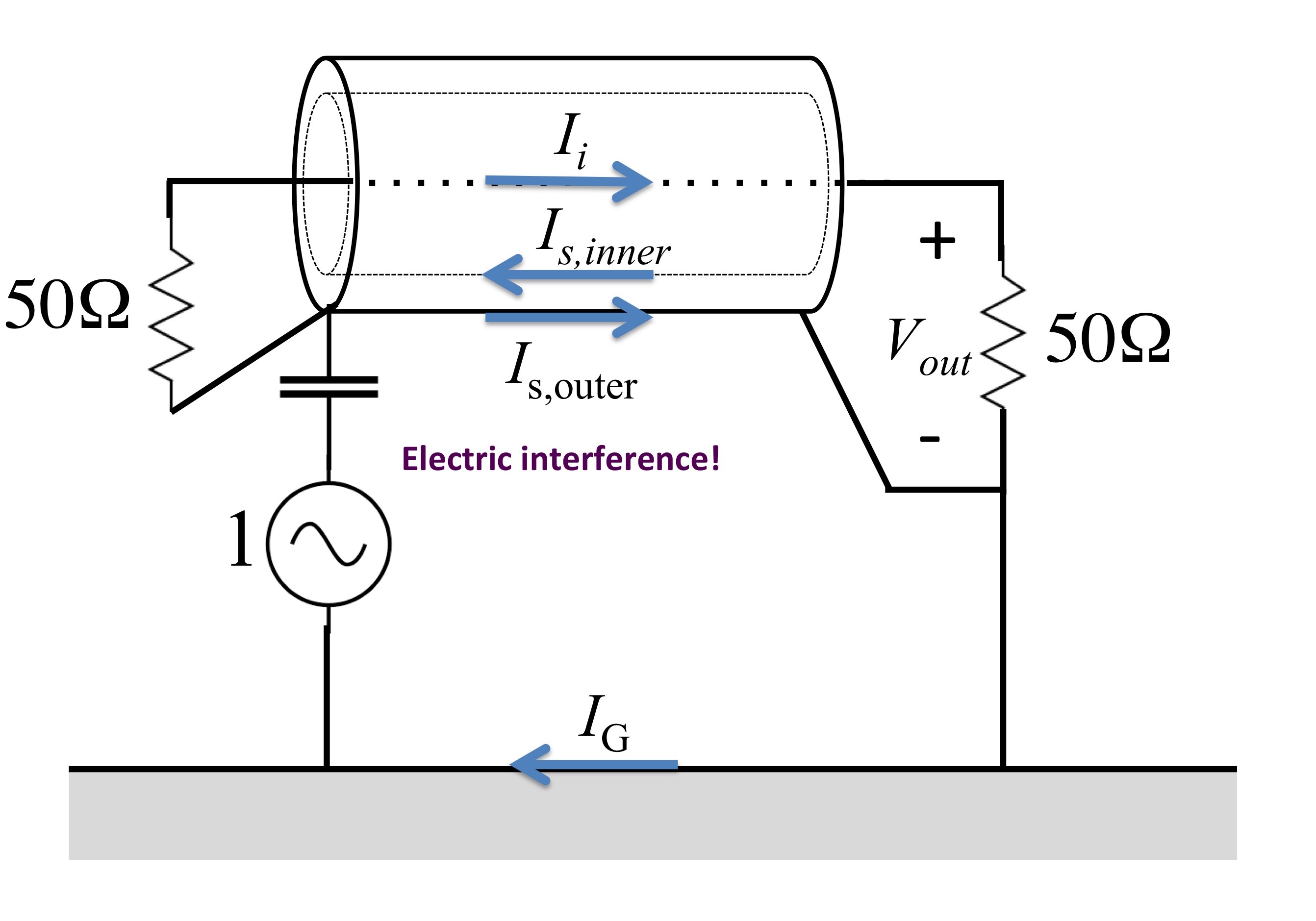
How does a wire connected to ground with a grounded "shield" around it react to electric interference (here the ground is on the opposite side of the interference point)? Click on the pic below to find out!
How does a floating coax react to electric interference (here the ground is on the opposite side of the interference point)? Click on the pic below to find out!
How does a coax grounded at one end react to electric interference (here the ground is on the opposite side of the interference point)? Click on the pic below to find out!
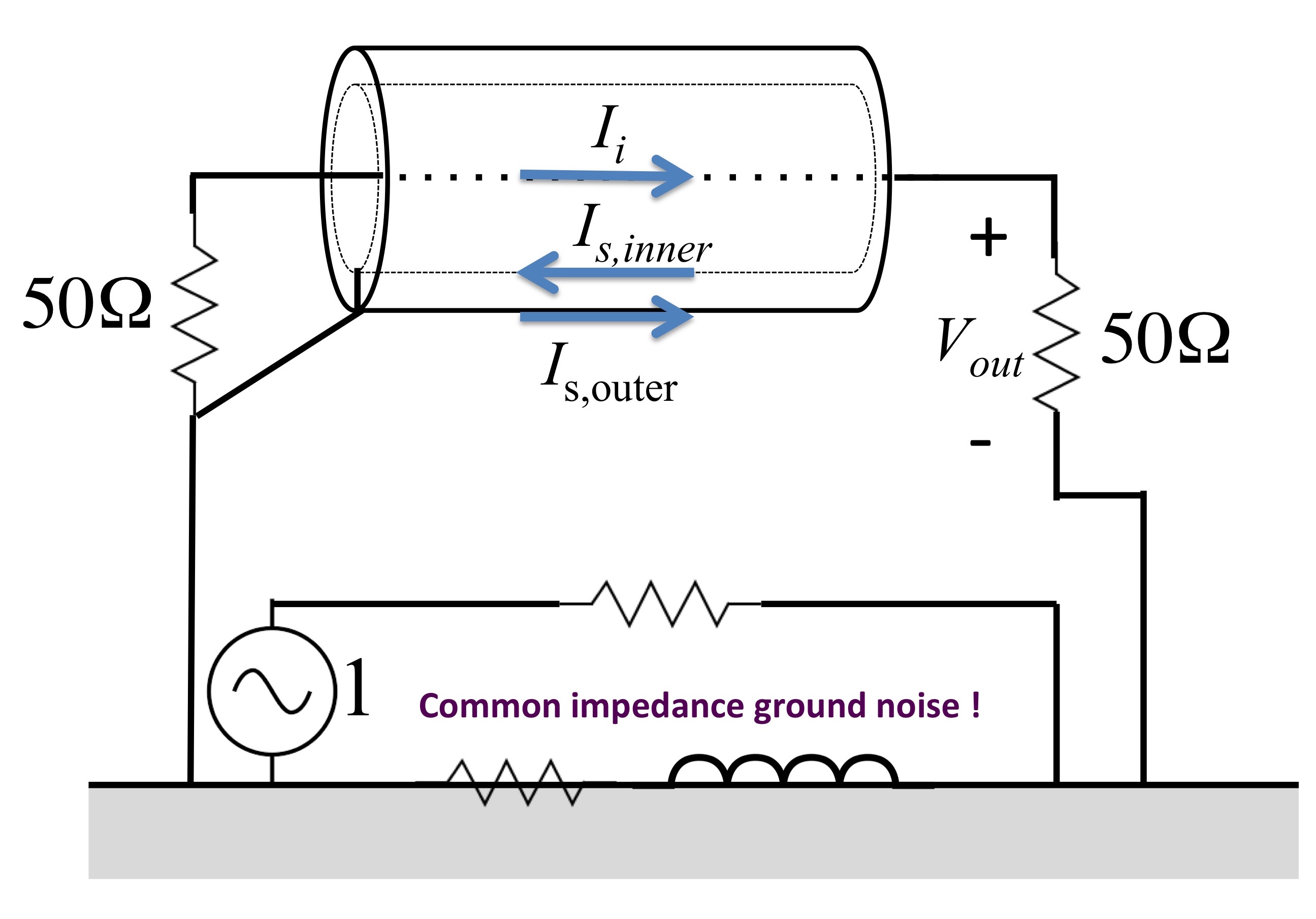
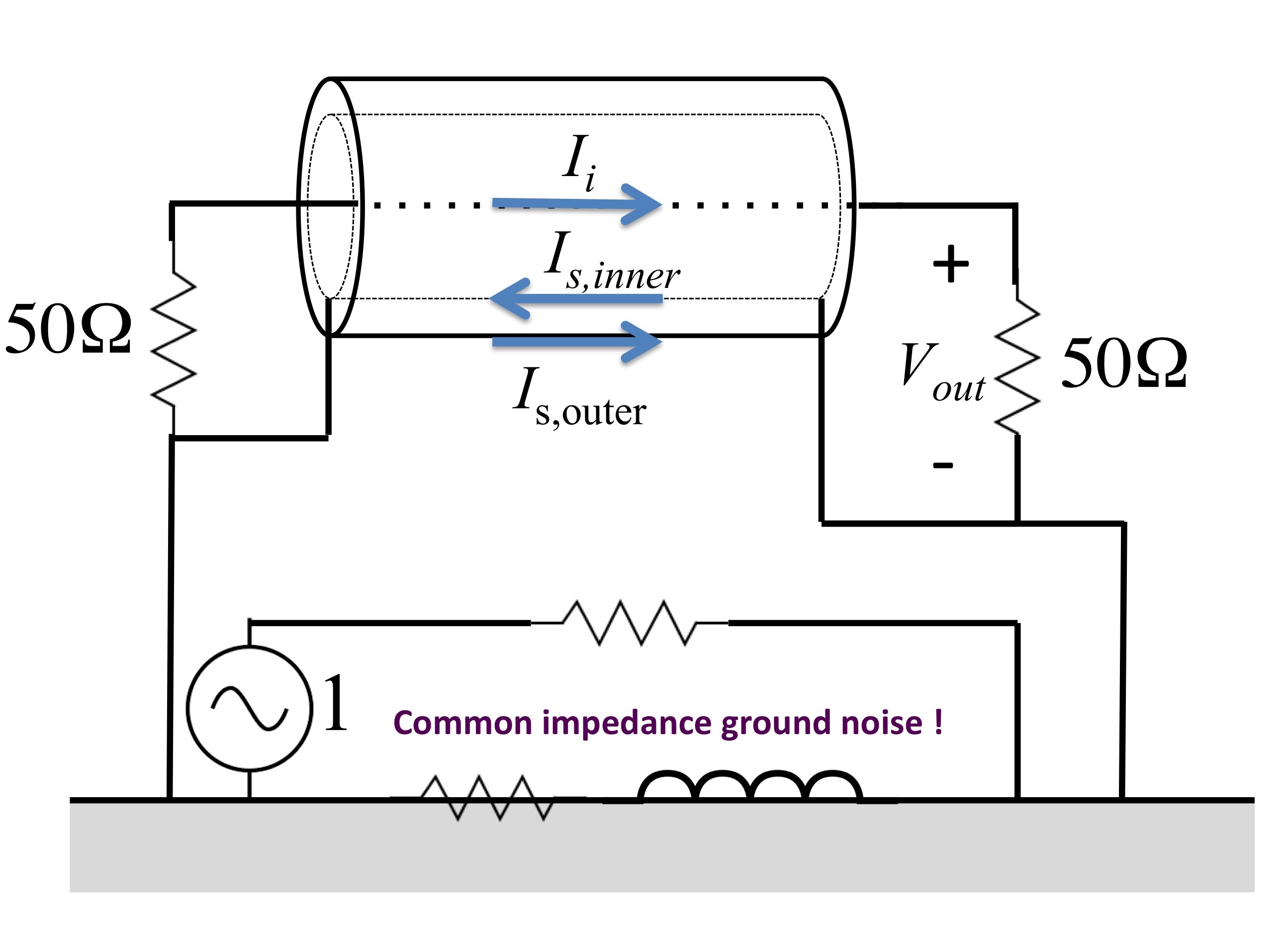
How does a coax grounded at one end react to common impedance ground interference? cCick on the pic below to find out!
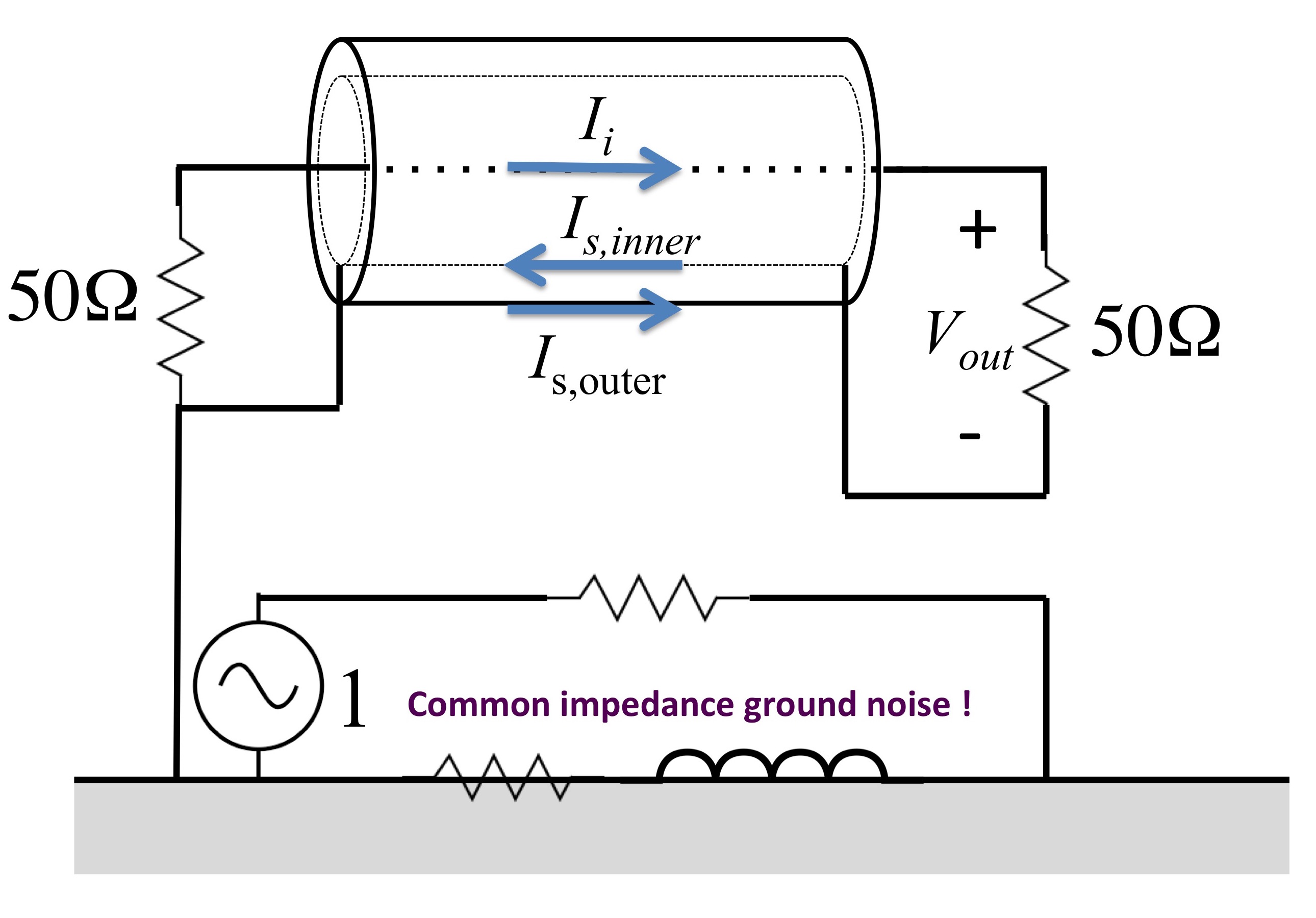
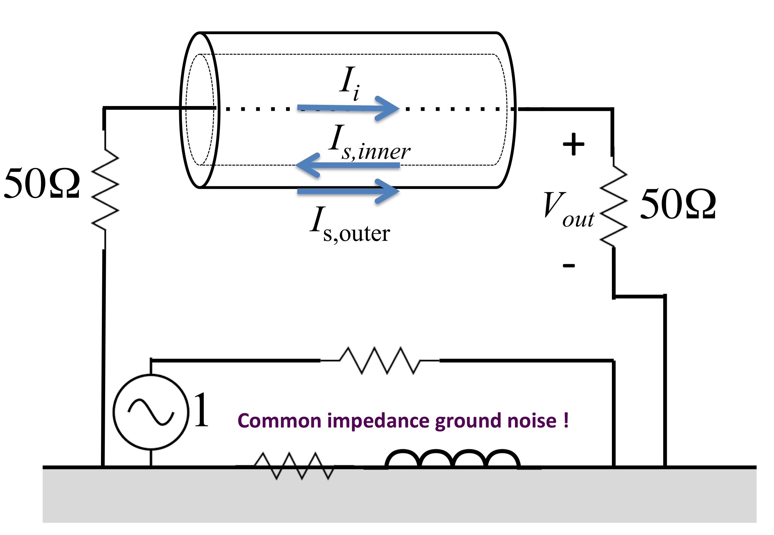
How does a coax grounded at both ends react to common impedance ground interference? Click on the pic below to find out!
How does a wire connected to ground with a floating shield react to common impedance ground interference? Click on the pic below to find out!
How does a wire connected to ground with a shield grounded at one end react to common impedance ground interference? Click on the pic below to find out!