Circuit a day: basic transformer
Prepared by Dr. Aaron Scher
[email protected]
Oregon Institute of Technology
Back to Aaron's home page.
Back to Circuit a day.
Prepared by Dr. Aaron Scher
[email protected]
Oregon Institute of Technology
Back to Aaron's home page.
Back to Circuit a day.
Figure 3 shows a Spice simulation setup for a 1:2 transformer. The purpose of this transformer is to double the voltage across the load ZL = RL (the load is purely real). In the simulation, the transformer is composed of two coupled inductors L1 and L2, with a maximum coupling coefficient k = 1. To simulate the ideal transformer, we must choose L1 and L2 to be very large ("large" in this case means that the impedance of the inductors at the operating frequency is much larger than the generator resistance Rg and the load impedance ZL.) The inductance of coils is proportional to the number of windings squared (N^2). Therefore, to simulate a 1:2 transformer, we choose sqrt(L2/L1) = 2, or L2=4*L1. In this example, the operating frequency is 1 kHz, the load ZL=1 kOhm, and the generator resistance is Rg=1 Ohm. Note that the grounds of both the primary and secondary sides are tied to a common ground. LTSpice flags an error if they are not both grounded. Also, note that the voltag across the load is not exactly 2 V. This is because the voltage across the primary side (side 1) of the transformer is slightly less than 1 due to the voltage drop across the source resistance.
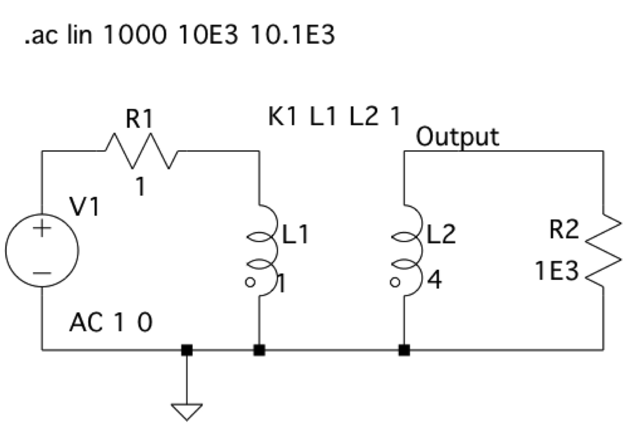
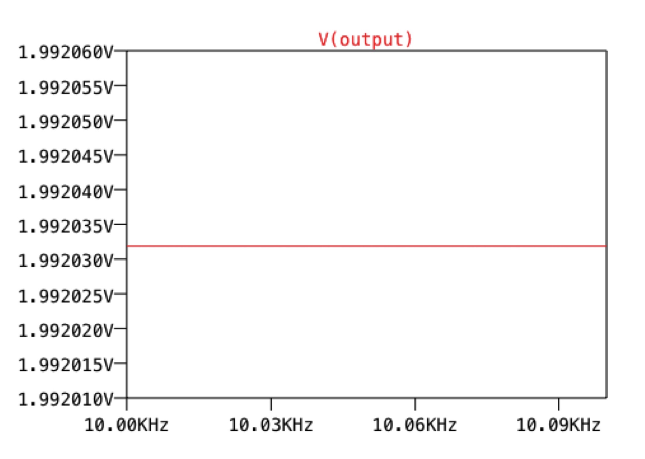
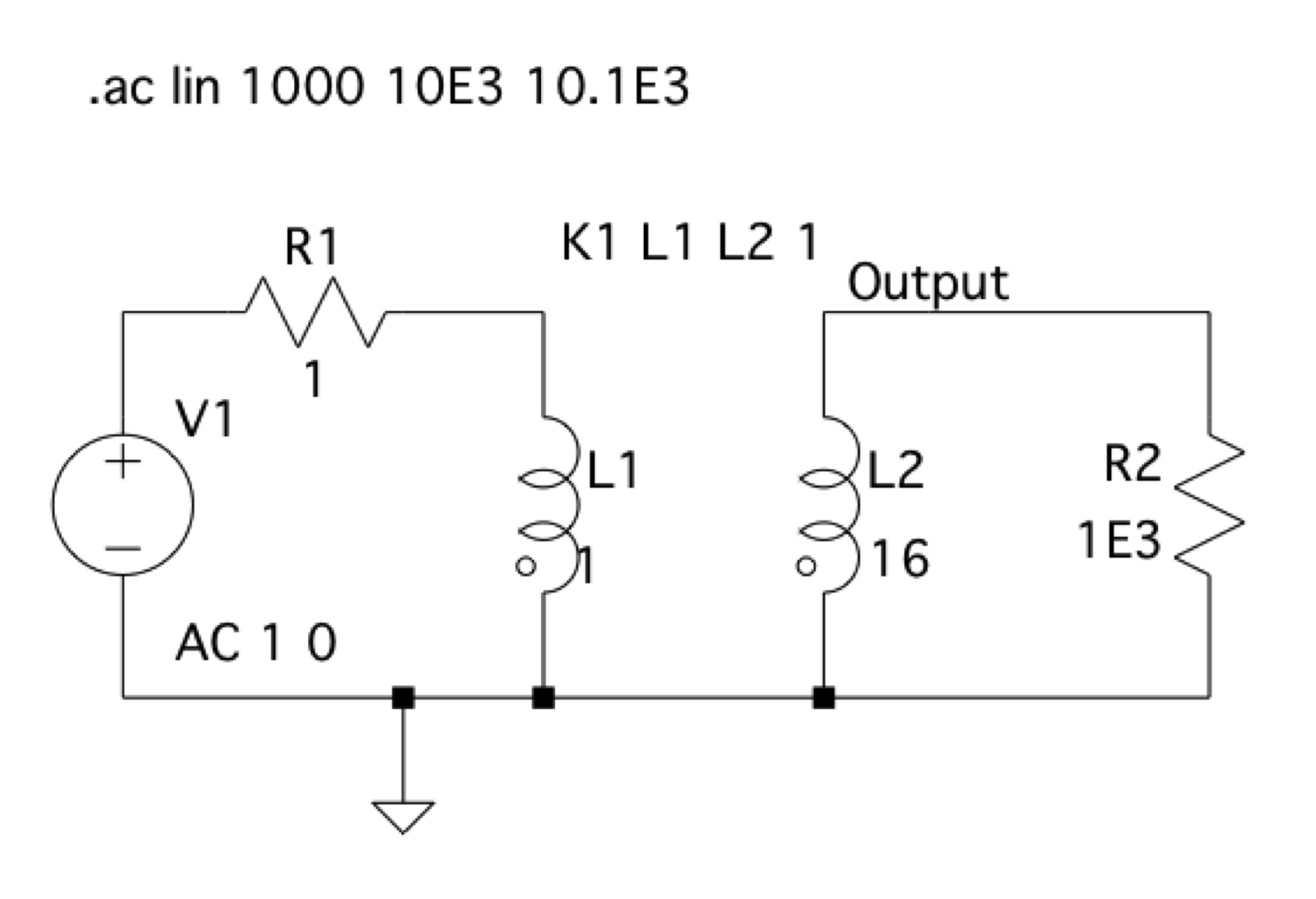
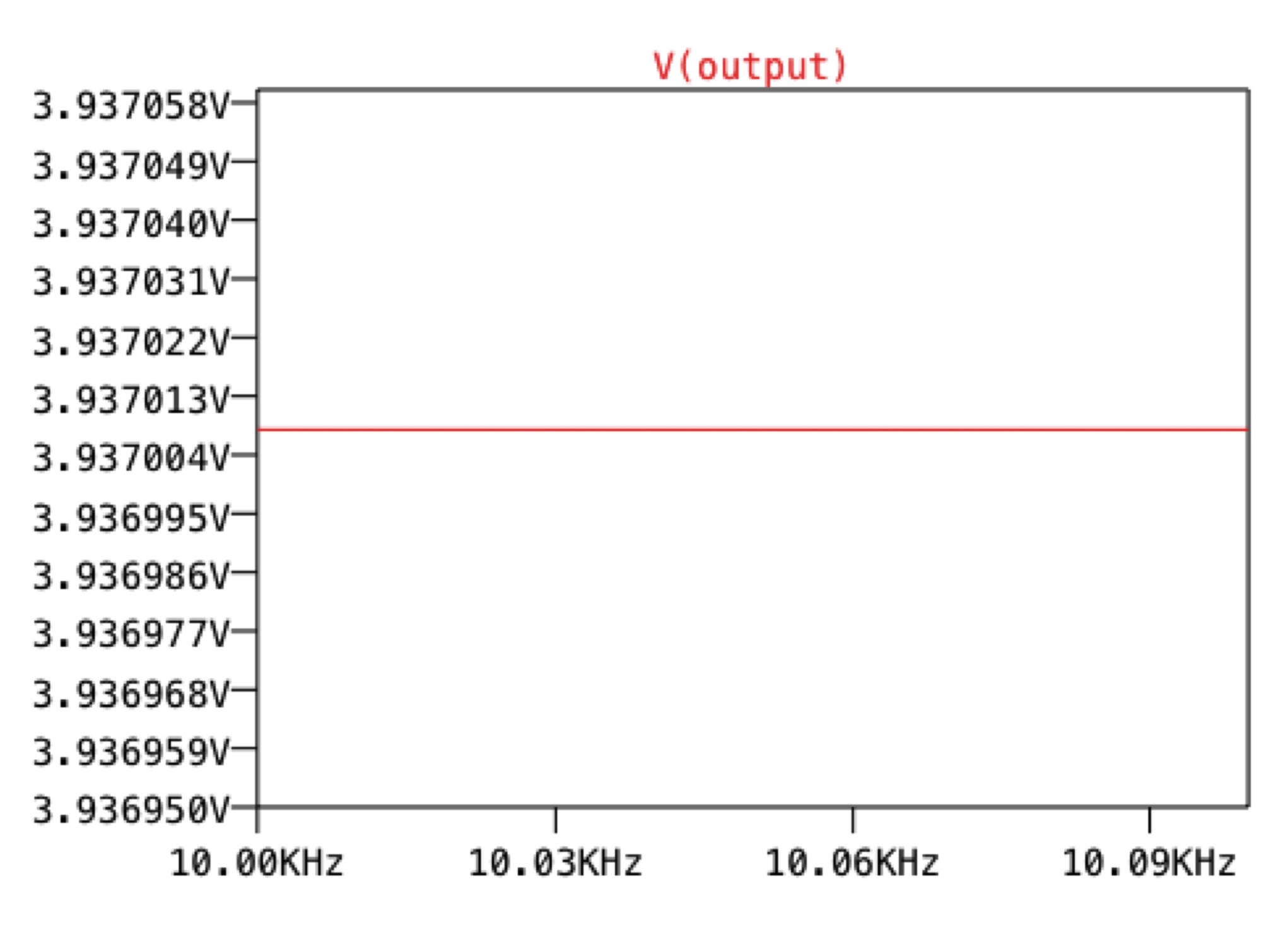
Figure 5 shows a Spice simulation setup for a 1:4 transformer. The purpose of this transformer is to quadruple the voltage across the load RL. In this case, L2/L1 = 4^2, or L2=16*L1. The voltage across the load is shown in Figure 6.
One might think that by increasing the turns ratio N2/N1 indefinitely, you can achieve any arbitrarily large voltage across the load ZL, but this is not true. The reason is that as you increase the turns ratio N2/N1, the impedance presented to the generator decreases, i.e. the impedance "seen" by the generator "looking" into the transformer decreases by the factor (N1/N2)^2 (the equation for the impedance transformation through an ideal transformer is presented in Figure 2.)
The maximum voltage you can obtain across the load occurs when the transformer is impedance matched to the generator impedance. That is to say, when the generator "sees" Zin = Rg, the voltage across the load ZL is maximized. Using the equation for the impedance transformation through an ideal transformer (see Figure 2), we find that the maximum voltage occurs when (N2/N1)^2 = (L2/L1) = ZL/Rg. This can only occur for a real load ZL = RL = Rg*(N2/N1)^2 = Rg*(L2/L1).
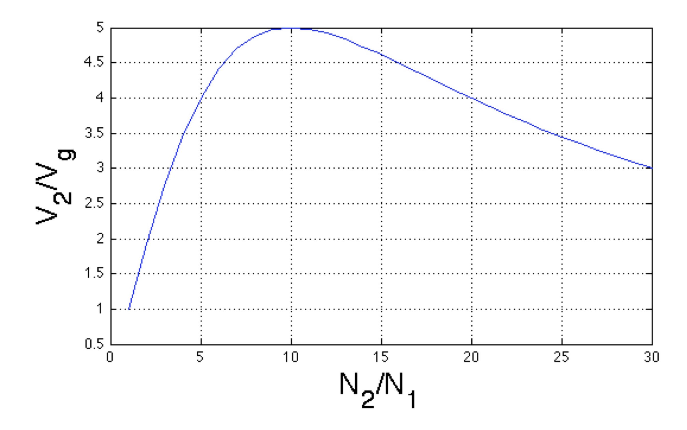
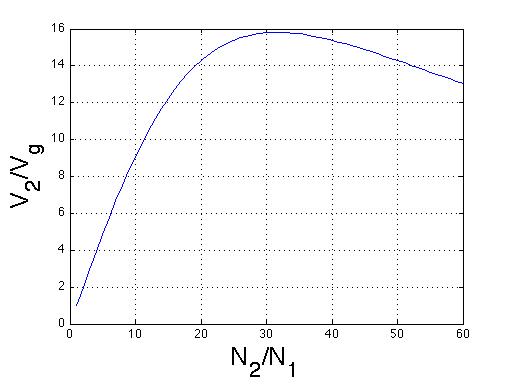
To demonstrate impedance matching, Figure 7 presents the voltage across the load as the turns ratio N2/N1 is increased from 1 to 200 (this plot was generated using MATLAB). For this plot, I set the generator resistance Rg = 1 Ohm and the load resistance RL = 100 Ohm. This plot was generated using the following equation for the voltage across the load:
V2 = (N2/N1)*Vg*Zin/(Zin+Rg),where Zin = ZL(N1/N2)^2. Note that V2 is maximized when N2/N1 = 100. Increasing the turns ratio beyonds this only DECREASES the voltage across the load. The current across the load is I2 = V2/RL. The means that the maximum current across the load occurs for the same turns ratio (N2/N1) in which the voltage is maximum.