Circuit a day: “Class C type” rectifier (single series-diode configuration)
Prepared by Dr. Aaron Scher
[email protected]
Oregon Institute of Technology
Back to Aaron's home page.
Back to Circuit a day.
Back to Diode Rectifiers.
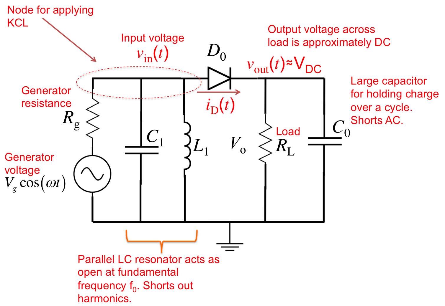
Below is an annotated schematic of the diode
simple rectifier with shunt inductor (series diode configuration).
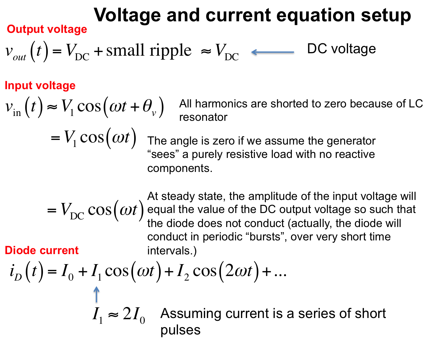
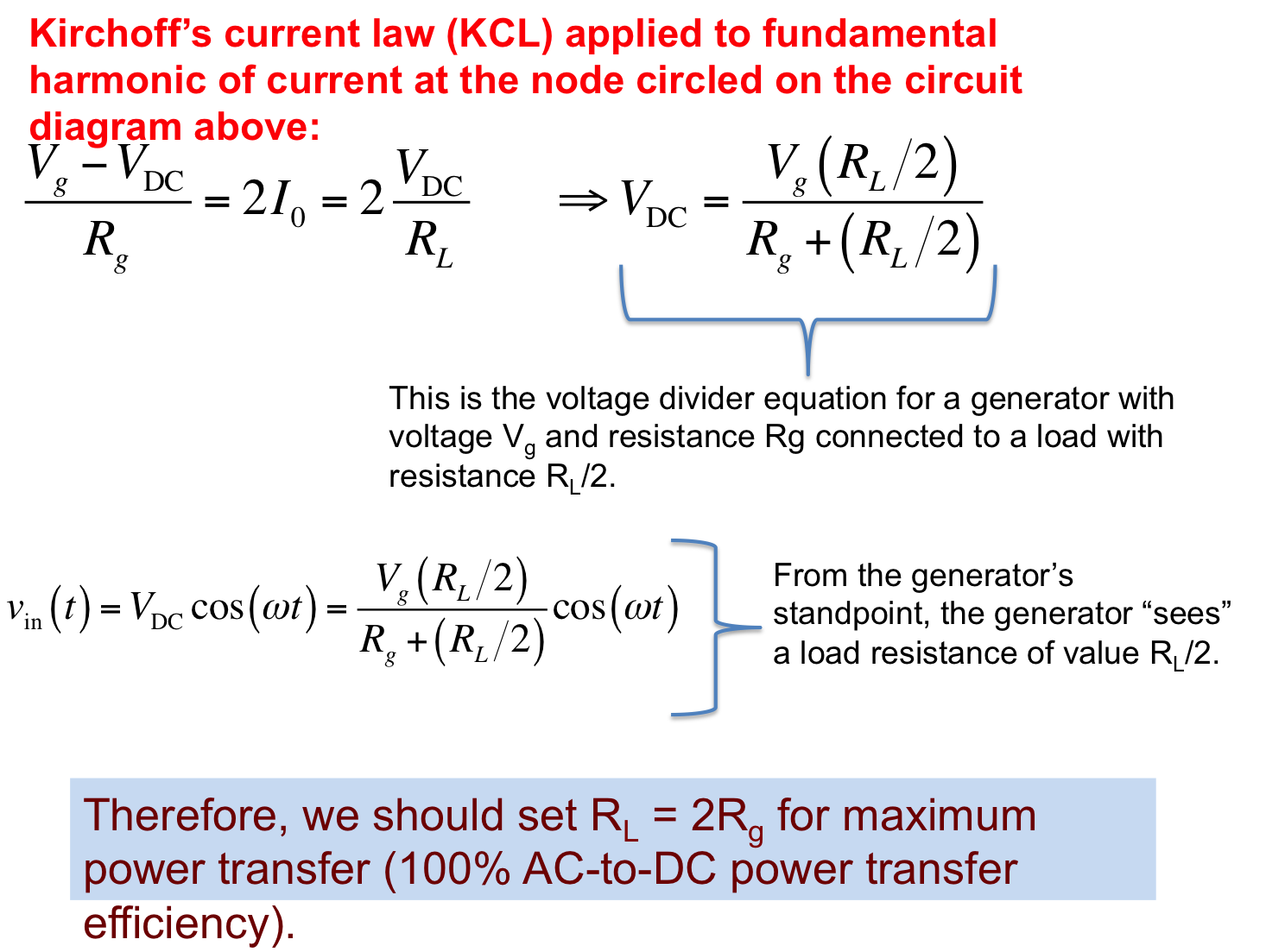
Below is a mathematical derivation to find the power conversion efficiency
of the diode rectifier circuit. Note that I am assuming an ideal diode with zero threshold voltage.
In the above equations, we have determined that we can achieve
100% power efficiency if the load resistance is twice the generator
resistance (i.e. RL = Rg).
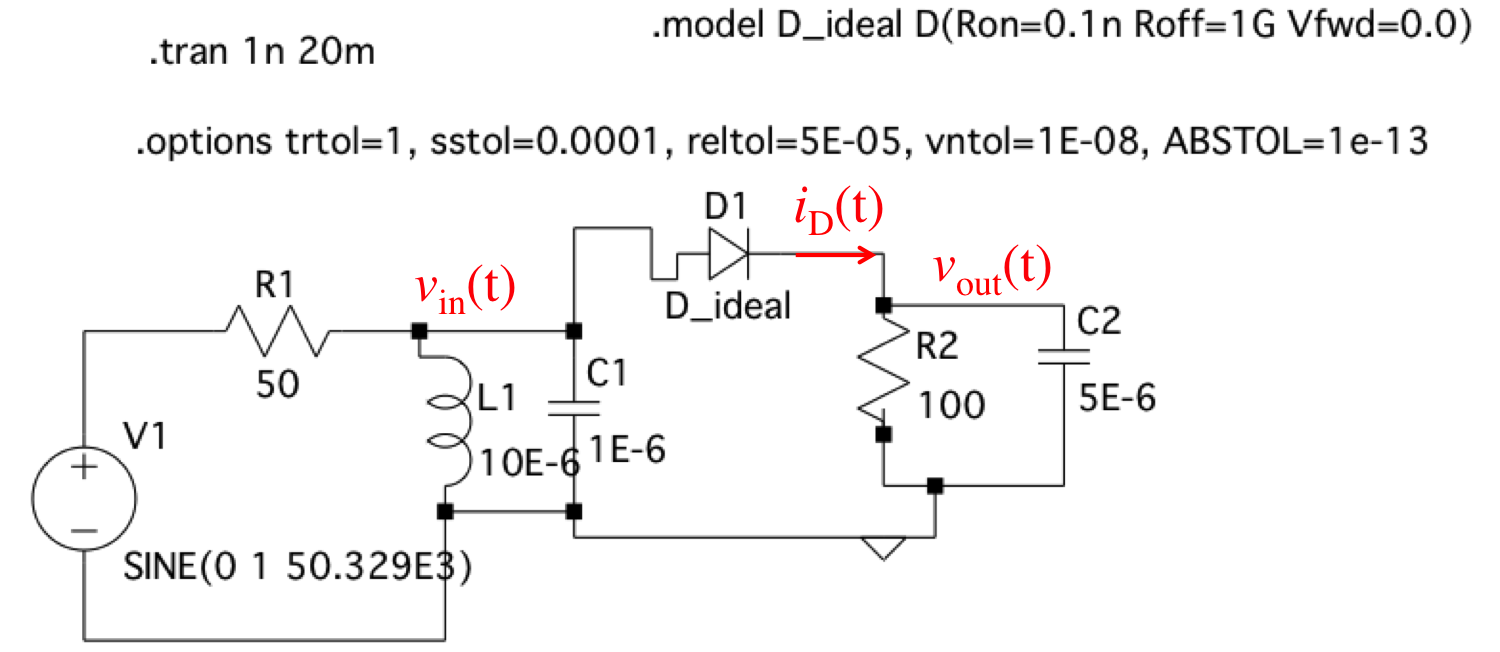
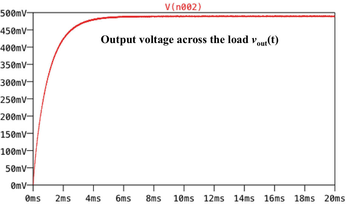
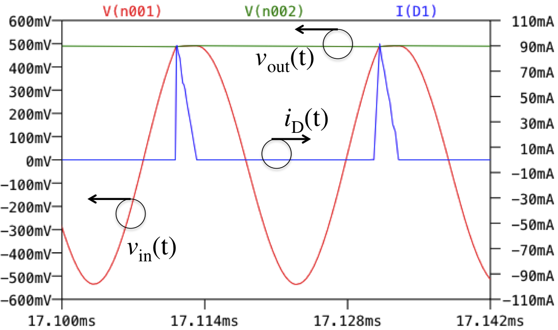
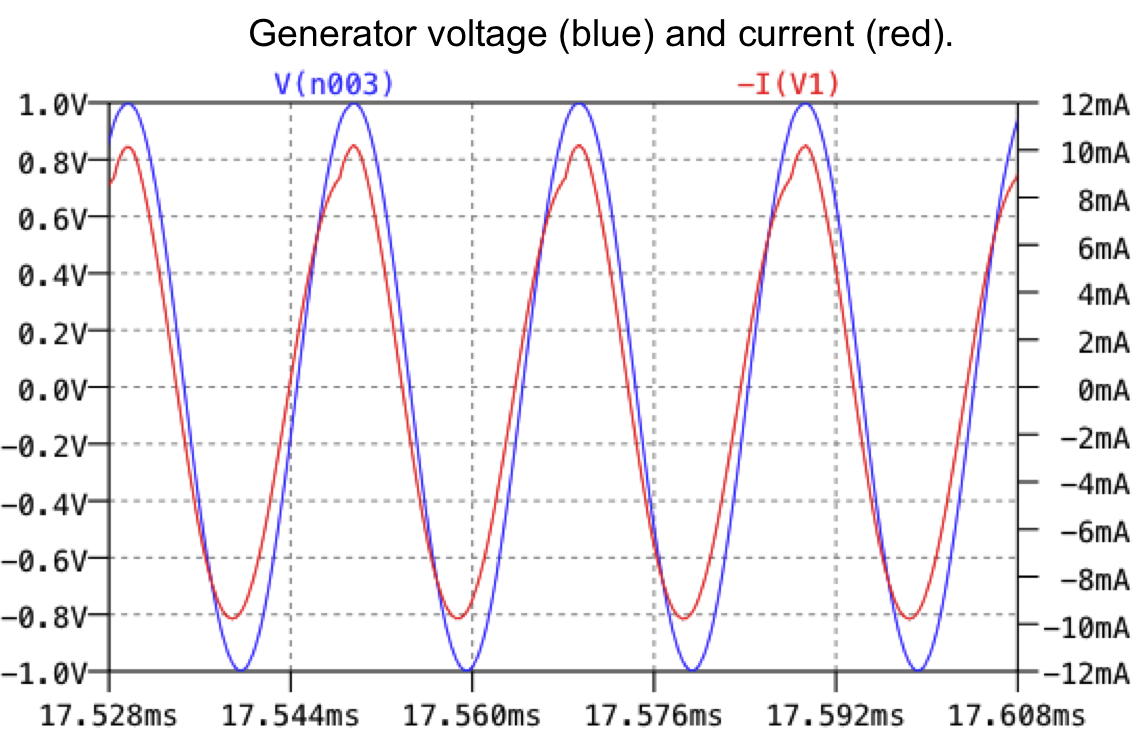
Below is an LTspice schematic used to verify our results. Here we have
Rg = 50 Ohms and RL = 100 Ohms. With this ratio, we
predict an efficiency of η =100%. In the schematic below, our voltage source amplitude is
1 V. This corresponds to an available power of: Pav = 1^2/50/8 = 0.0025 W = 2.5 mW. The plots
show that the output DC (average) power across the load is about VDC = 490 mV.
This corresponds to an average power dissipated across the load PL = .490^2/50 = 0.0024 W.
Hence, the efficiency as determined using LTspice is PL/Pav = 0.0024/0.0025 = .96 = 96%, which agrees
quite well with the theoretically predicted result of 100%.