
Back to Aaron's home page.
Back to Circuit a day.
Here we present the design equations for an inductive wireless power system consisting of lossless coils with primary and secondary circuits tuned to the same resonant frequency.
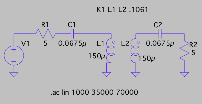
In this example, we will design a simple inductive wireless power system. The source resistance is 5 Ohms and the load resistance is 5 Ohms. The inductors L1 = L2 = 150 uH. The frequency of operation is 50 kHz. What should be the value of the capacitors? What should be the coupling coefficient?
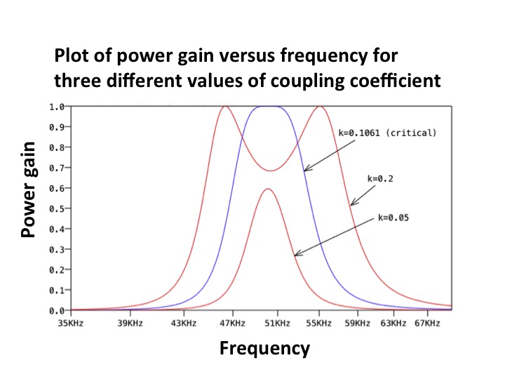
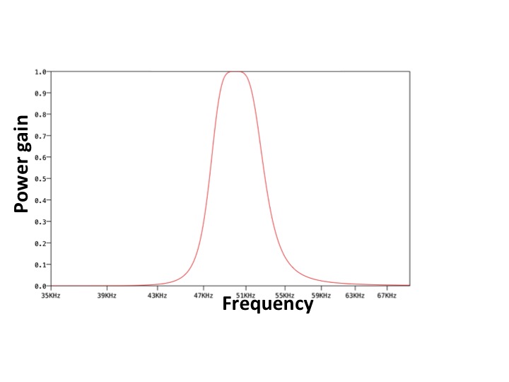
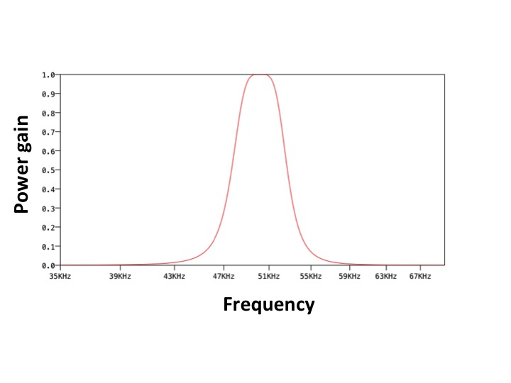
Figure 2 shows the Spice schematic. Figure 3 shows plots of gain G of the system (G = Pload/Pgenerator)
over frequency for three different values of
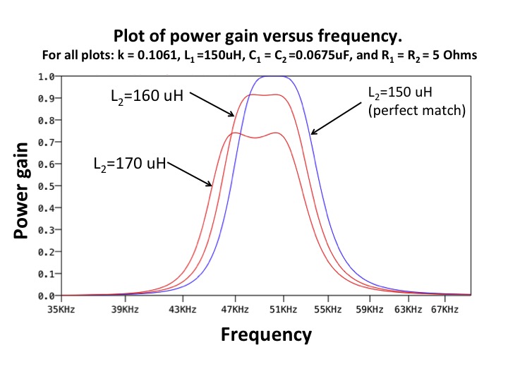
the coupling coefficients k. Figure 4 demonstrates how component tolerances could easily degrade performance
in this system. Here we plot the gain G of the system for k= 0.1061 (critical coefficient of coupling),
and vary the inductance of circuit 2 (L2), while leaving everything else the same.
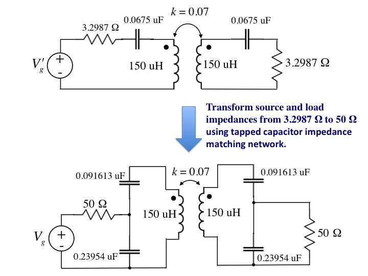
In this example, we will design another inductive wireless power transfer system. The source resistance is 50 Ohms and the load resistance is 50 Ohms. The inductors L1 = L2 = 150 uH. The frequency of operation is 50 kHz. The coupling coefficient is specified to be k = 0.07.
This problem is different than Example 1, because not only are the source and load resistances given, but also the coupling coefficient k. To solve this problem, we are going to have to add additional impedance matching circuitry on both the input and output side of the basic inductive wireless power transfer system shown in Figure 1. Let us ignore for a moment that the source and load resistances are specified to be 50 Ohms, and find the proper load/source resistance R' that corresponds to k = 0.07. Assuming both circuits 1 and 2 are equal, such that Q1=Q2=Q= ω0L/R', where L = 150 uH, we can solve for R':
k=1/sqrt(Q1*Q2)=1/Q=R'/(Lω0) → R'=kLω0 → R'=3.2987 Ohms
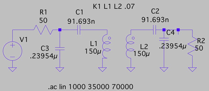
Figure 5 shows the prototype wireless power transfer system with both source and load resistances equal to R'=3.2987 Ohms. In this figure we also demonstrate the use of the "tapped capacitor" impedance transforming network for transforming R' into the required 50 Ohms. This tapped capacitor transformation is accomplished using the series RC to partial parallel RC transformation presented in Series-to-parallel impedance transformation. Figure 6 shows the Spice schematic of our final circuit and Figure 7 shows the gain (simulated in Spice).
There are many alternative options to the
tapped-capacitor impedance matching network presented above.
Figure 9 demonstrates the use of magnetically coupled inductors for transforming
R'=3.2987 Ohms into the required 50 Ohms.
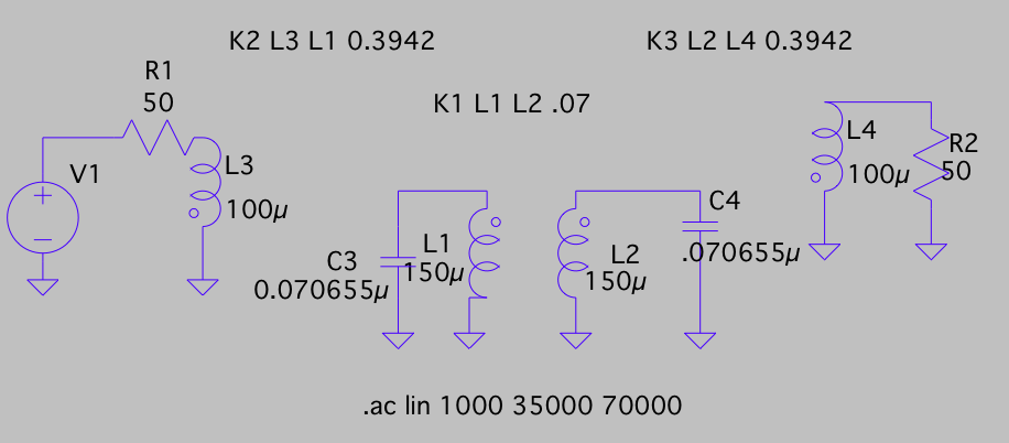
Figure 10 shows the Spice schematic of our final circuit, and Figure 11 shows the gain (simulated in Spice).
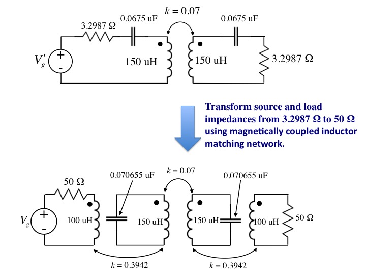
Transforming the source and load resistances using magnetically coupled inductors.
[1]F. E. Terman, Electronic and Radio Engineering, McGraw-Hill Inc., NY, 1955. See Section 3-5.