Back to Aaron's home page.
The series-to-parallel impedance transformation is a very useful tool for analyzing matching networks composed of inductors and capacitors.
Figure 1 shows the transformation between a general series circuit (with series resistance Rs and series impedance Xs) and a general parallel circuit (with shunt resistance Rp and shunt impedance Xp). The Q-factor of the series circuit (Qs=Xs/Rs) and the Q-factor of the parallel circuit (Qp=Rp/Xp) are generally frequency dependent. The transformation is only valid at one frequency f0 where QS=Qp. The bandwidth of this circuit (i.e. the range of frequencies around f0 where this transformation is accurate) increases as Q is lowered.
Figure 2 shows the transformation for RL circuits.
Figure 3 shows the transformation for RC circuits.
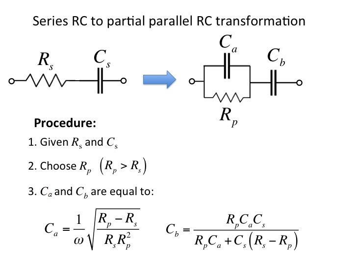
Figure 4 shows how to transform a series RC to a partial
parallel RC circuit. Click here for a derivation