Two magnetically coupled inductors have many alternative circuit representations that are useful for impedance matching and transformations.
This page presents some of my favorites. Here we assume "ideal" components, meaning we ignore the resistance of the coils and any stray capacitance
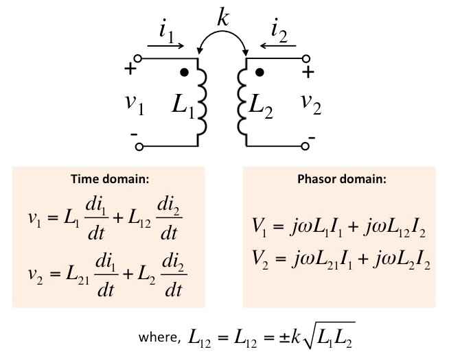
that may exist. Figure 1 shows a schematic diagram of the coupled inductors along with their current-voltage relationships. Figure 2 shows
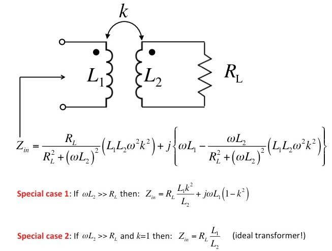
how the magnetically coupled inductors transforms the impedance of a real load. Note that, in these figures, the coupling coefficient k is positive if both currents (i1 and i2)
enter or both leaving through a dotted terminal. The coupling coefficient is negative if one current enters through a dotted terminal, while the other leaves
through a dotted terminal.
Figure 1. Schematic diagram of magnetically coupled inductors.
Figure 2. Magnetically coupled inductors transforms the impedance of a real load.
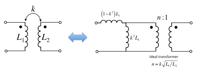
Equivalent circuits
Transformer model
Figure 3. Equivalent circuit with ideal transformer model.
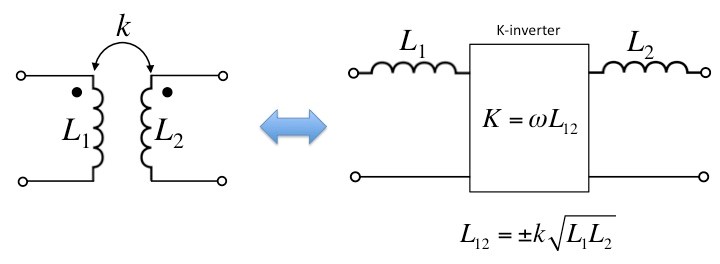
Impedance inverter model
Figure 4. Equivalent circuit with impedance inverter (also called the "K-inverter").
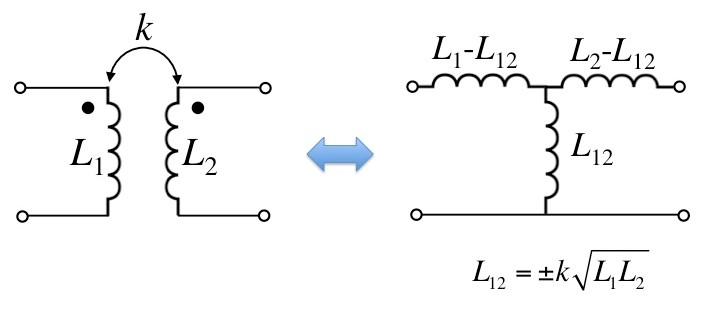
T-configuration
Figure 5. Equivalent circuit with lumped element T-configuration.